Game of Life on cheap 8x8 RGB LED Matrices

Game of Life on cheap 8x8 RGB LED Matrices

Game of Life on two Cheap SMD Practice LED Matrices

256 LED SMD “Practice” Board
I can’t resist a ridiculously cheap LED matrix (as might be apparent by now), so when this popped up in the usual enticing “deals” section of a popular overseas electronics store, I must admit I was weak 🙂
It is described as some combination of the following:
And variations thereof.
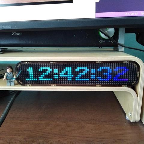
It is typically available for around £3-4 for the 256 LED version and £2-3 for the 64 LED version. One thing I thought was quite interesting is that the LEDs go right to two edges of the PCB so that does make me wonder if a couple of these could be tiled together.
It also includes a breakout header hinting at the possibility of customisation.
https://makertube.net/w/dRN6hyoHKTXez2PwyKs1A4
The Circuit Design
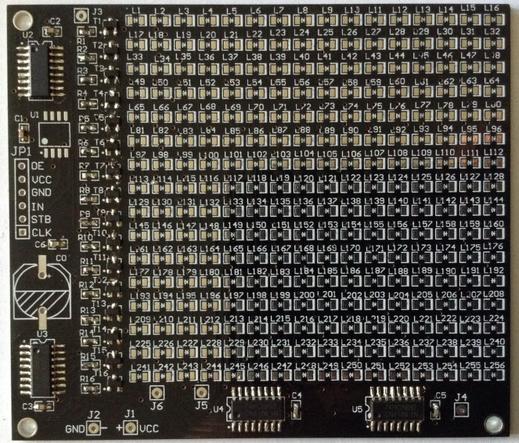
There is a bit of information online, but not as much as I’d like. Essentially it is a microcontroller, some 595 shift registers, driver transistors, LEDs and a few ancillary components in what would probably be a fairly standard arrangement. There is a low-res schematic I’ve found:
The bill of materials names the 8-pin microcontroller as a DX156, but I can find no information about it online. Interestingly though, all six pins that are used in the circuit are broken out to a header, so if the microcontroller is left off the board, I don’t see why it wouldn’t be possible to drive the shift registers directly via the header.
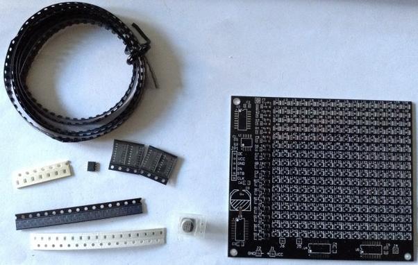
The full BOM is as follows:
There is a comment in the description of the kit about changing the display:
” If you want to change the display content, you can connect the control signal from interface JP1 without soldering the included microcontroller, and any content can be displayed. (You can refer to the relevant information of our store’s 16 * 16 dual color dot matrix, which is consistent with the interface of the microcontroller. This interface needs to be provided by oneself and is not included in the kit.)”
But I’ve not found who the “our” is in “our store” or which kit/module is being referred to, so I’ll come back to that in a bit. Again this confirms that for now, I’ll leave the MCU off until I’ve decided what to do.
Other things I note from the schematic:
An LED will be on when the Hn signal is LOW and Rn signal is LOW. This is because Hn going LOW will allow the PNP transistor to conduct, thus making In HIGH. when In is HIGH and Rn is LOW the LED will light up.
Building the Kit
The approach to take for building should be relatively obvious. It will just take a fair bit of patience! One initial consideration – do I test each LED prior to soldering, or just go for it and rework anything that might not work…
Everything apart from the 100nF capacitors and resistors has a polarity to watch out for.
I’ve decided to fix the non-LED components first, thinking that I can then test each row of LEDs as I fix them to ensure they all work before moving on. So I built it in the following order:
I’ll save the electrolytic until last, as it is presumably just for stability of the power supply, which can be external for now. And I think I’ll leave the MCU off for the time being too. I might use a SOP-8 to DIP breakout to allow me to use it to drive the board via the header.
Note: after starting on the LEDs, with hindsight, soldering on the header was a mistake. It allows me to test the board, but it means the board no longer sits perfectly flat on the desk whilst working on it. Something to consider for any similar activity in the future.
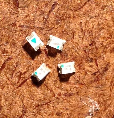
Determining the polarity of the LEDs is slightly challenging, but there is an arrow on the back, and if one looks carefully a dot on the front, that both indicate the cathode (line). When assembled in the orientation shown below, the dot is on the right-hand side (excuse my dodgy soldering – this is meant to be a soldering practice kit after all).
After one row I took a break to get some code running (see below). Then added three more rows and am now taking a longer break! Its slow, but steady progress 🙂
Initial Testing
The initial plan, once built and shown to be working, was to reprogram the microcontroller, but seeing as there is next to nothing published online about the DX156, it would be a lot easier to replace it with a SOP-8 footprint microcontroller that I already know how to use.
Unfortunately the pinout of the footprint doesn’t quite match with something like an ATtiny85… it’s close, so I don’t know yet if that would be an option.
Anyway, I’ve left off the provided microcontroller and for initial testing am driving the board via the 6-way header.
I anticipated just using the provided microcontroller on a SOP-8 to DIP-8 breakout but couldn’t find one to hand (I’ve definitely got one somewhere), but that will have to come later, as I now have one on order.
Instead, after soldering on one row of LEDs, I jumped into hooking it up to an Arduino which meant I had to figure out how to drive it myself.
Programming
The 74HC595 has the following pinout
The basic use in a circuit requires the following:
74HC595 pinFunctionHeader pinPCB or ArduinoVCCVCCVCC+5VSER (or DS)Serial / data inIND11/OEEnableOEGNDRCLKLatch (Storage register clock)STBD8SRCLKSerial clockCLKD10/SRCLR (or /MR)Clear / master re-clearN/C+5VQH’Data outN/CNext 595 in the chainGNDGNDGNDGNDQA-QHIndividual outputsN/CThe LEDsGiven how everything is connected according to the schematic, the decoding works as follows:
This all means that a 32-bit value encodes the ROW/COLUMN information as follows:
Bit: 31...24 23...16 15...08 07...00The algorithm to push data out to the shift registers is thus as follows:
void shiftWrite32 (uint32_t data) {Note the use of “1UL”. Without the “UL” this does not appear to get extended to a full 32-bit value. This gave me quite a bit of grief, until I hooked up an oscilloscope to CLK and DATA and could only see half the data getting written out!
At some point this would be worth re-implementing using PORT IO, but the use of digitalWrite will do for now.
This means I can cycle through each column of LEDs with the following code:
uint32_t dataval;This will continually set one of the top 16 bits LOW in turn, whilst keeping all lower 16-bits LOW, thus illuminating each column in sequence. This will light up all completed rows as I’m doing nothing to select the row yet.
Note again the use of “UL” to force 32-bit arithmetic.
Here is a more complete version that now includes selecting the row too.
uint32_t dataval;In both cases the default “off” state is a bit high (so 0xFFFF for each of the 16-bit chunks). To select a row and column, the corresponding bit has to be set to 0, hence using ~(1<<bit) which is NOT (bit).
Scanning the Display
The above is all fine for some simple tests, but really I need a simple way to scan the display independently of any running code and for that, the best way is to use a timer interrupt to trigger the updating of the display.
#include <TimerOne.h>This uses the same shiftWrite32() function, but now it is called for all rows every 20 ms using the TimerOne library.
The use of shiftWrite32(-1) is a simple way of clearing the display as it will set all bits HIGH. I have to do this at the end of the shiftUpdate() function to clear the display after the last row update, otherwise the last row will remain lit until the next shiftUpdate scan. This makes the last row appear brighter than all the rest as it is on for slightly longer.
I’ve used 20,000 in the call to Timer1.Initialize() as 20mS appears to give a good balance between a flicker free scan of the display whilst allowing some spare CPU time to actually run the loop. I’m still using the relatively slow digitalWrite() function calls in the shiftWrite32() function, so this is one area for obvious performance improvements if I need to do something better.
There is no buffering between writing to the disp[] “screen” array and actually updating the display, so it would be quite possible to get a screen update partway through calculating a new display. If this becomes an issue then it would be possible, memory permitting, to use a double-buffering arrangement and ensure the screen buffer that is written to the display is never the one being written to by the main loop, but I’ve not bothered about that right now.
Conclusion
After realising that reprogramming the original MCU wouldn’t be an easy thing to do, I did wonder about the utility of this board, but actually driving it from an Arduino turned out to be relatively straight forward.
In the end, my total SMD parts count was:
I’d say that was a success for me.
Kevin
#arduino #gameOfLife #ledMatrixGame of Life on a Cheap SMD Practice LED Matrix

Testing a Cheap SMD Practice LED Matrix Kit

Mini 8×8 LED Matrix
I have a few neat 20x20mm square 8×8 LED matrix modules that I want to drive.
Quite some time ago I tried to hook them up with a HT16K33 based 16×8 I2C LED matrix driver, but it was all on stripboard and not only was it quite messy, actually it really didn’t work very reliably either, so this is another attempt. Eventually this resulted in a small driver PCB.
The LED Matrix Module
The fundamental point of an LED matrix module is the matrix bit. The LEDs are arranged in a grid of some sort and consequently it isn’t possible to light up all LEDs at the same time. They have to be “scanned” and if they are scanned quickly enough then persistence of vision kicks in and it appears as if all LEDs are lit at the same time.
There are a whole range of 8×8 LED matrix modules to choose from, and often it isn’t obvious what the type or pinout for them is. At least it isn’t when they’ve been kicking around in your parts drawer for some time.
Options are:
Here is a schematic with LED arrangement and pinouts for a common 8×8 LED module found very cheaply online.
The left shows a common cathode, and the right a common anode. I’m pretty sure I have common anode LEDs from an old note I found lying around, so I’m going to start with that.
I’ve used the following simple circuit to verify which pin is which. The resistor is there to limit the current passing through each LED.
In the final circuit, I’d be looking at maybe using a 1K resistor so limiting the LED current to around 3-3.5mA (assuming 5V supply and forward voltage of 1.7-2.2V for a typical red LED). For a maximum of 8 LEDs per common connection, that would still only be less than 50mA so I don’t think current would be an issue in any of the approaches I’ll be looking at. But I also have to take into account that if there are 8 scan cycles for a complete display, then each LED will only be on for 1/8th of the time of the scan, so will appear 1/8th as bright anyway.
I do seem to have a module that follows the pinout as shown above (right). In the following diagram, the pins are numbered with pins 1 to 8 along the bottom (left to right) and pins 9 to 16 across the top (right to left).
In this orientation, the ROWs and COLUMNs as described above are mapped as shown below.
Just to bring all this together, the pin functions of my matrix are as follows (row = anode; column = cathode):
PinPinR5116C8R7215C7C2314R2C3413C1R8512R4C5611C6R6710C4R389R1LED Matrix Driving
The fundamental principle for a common anode configuration is that if a positive voltage is patched onto a ROW and GND is connected to a COLumn then that LED at that position will light up. However of course, different ROWs and COLs will have different states so some kind of “scanning” will be required.
A microcontroller can do this without any additional support if it has 16 IO pins. For example, the following algorithm could be used to scan each ROW in turn, setting the appropriate COL values:
Initialise ROW and COL pins as OUTPUTEvery COL/ROW LED will light up when the combination ROW=HIGH, COL=LOW is reached. If the ROWs are scanned quickly enough, then persistence of vision means that the LED matrix appears to be fully illuminated.
As I say, given suitable current limiting LEDs (one per ROW) and enough IO pins a microcontroller could do this directly, but it uses a lot of GPIO and is likely to reach the current limits of the microcontroller pretty quickly if lots of LEDs are illuminated at once.
The answer is to utilise an additional chip as an LED matrix driver, both freeing up the microcontroller’s GPIO and providing the option for a higher current draw.
LED Matrix Drivers
There are a number of options. Some are general IO expanders, some are dedicated to supporting LED matrices, some include higher current sinks or sources as required.
A key benefit of these types of devices is that in some the scanning is performed by the device itself, so the MCU only has to send it the data for the complete display and then let it just get on with things.
MAX2719 Segment Display Driver
This is a “Serially Interfaced, 8-Digit LED Display Driver” (more here). From the MAXIM datasheet:
“The MAX7219/MAX7221 are compact, serial input/output common-cathode display drivers that interface microprocessors (µPs) to 7-segment numeric LED displays of up to 8 digits, bar-graph displays, or 64 individual LEDs.”
They interface to a MCU using SPI and have additional features to directly support 7 or 8-segment displays. As they support up to 8 digits with up to 8 segments, they could also perfectly support my 8×8 LED matrix.
Key parameters:
These are often paired up with a 32mm 8×8 LED display on a cheap PCB kit. For my purposes though, there is an issue – these are designed to be used with common cathode displays.
I suspect this is due to the current ratings for the digit/segment pins. The datasheet expands:
“Eight-Digit Drive Lines that sink current from the display common cathode. The MAX7219 pulls the digit outputs to V+ when turned off.”
“Seven Segment Drives and Decimal Point Drive that source current to the display. On the MAX7219, when a segment driver is turned off it is pulled to GND.”
If the LEDs are in a matrix, in principle it ought to be possible to have an arrangement that could work with a common anode display if the current limits can be balanced.
The common cathode (DIG) will assume a worst case of all 8 LEDs illuminated, meaning a maximum sink of up to 500mA or up to around 60mA per LED. The individual anode (SEG) supports up to 100mA current source per LED. These are both pretty high, especially as I’m not anticipating more than a total of around 50mA for 8 LEDs.
But can a common cathode scanning chip be used with a common anode display? As it stands it will be assuming that it can set a single cathode line LOW and drive all 8 anode lines according to the required pattern. But as the LEDs are displayed in a matrix, looking back at the circuit diagrams, I think it just means that the cathodes are the columns and the anodes are the rows. So instead of scanning rows, it will be scanning columns, so I think it would be fine.
So to summarise, for my LED matrix, the ROWs will be the anode, so connected to SEG and the COLs will be the cathode so connected to DIG.
There is one other key advantage to using the MAX7219. It supports a single “current setting” resistor (Rset in the datasheet). A single resistor between the ISET pin (18) and VCC. Looking at the table in the datasheet I think using a ~60-80K resistor would keep he current down to <10mA for the LEDs, although I must admit I’m not quite following how the values are calculated.
IS31FL3731 LED Driver
The actual IS31FL3731 driver chip is a QFN-28 or SSOP-28 surface mount device, so I won’t be using these directly, but they are available in a breakout board from Adafruit (more here and here). From the datasheet:
“The IS31FL3731 is a compact LED driver for 144 single LEDs. The device can be programmed via an I2C compatible interface. The IS31FL3731 offers two blocks each driving 72 LEDs with 1/9 cycle rate. The required lines to drive all 144 LEDs are reduced to 18 by using the cross-plexing feature optimizing space on the PCB. Additionally each of the 144 LEDs can be dimmed individually with 8-bit allowing 256 steps of linear dimming.”
I believe by “cross-plexing” they are talking about “Charlie Plexing”. The breakouts have the following key parameters:
These are available relatively cheaply (~£6 each) but they aren’t geared up for use with a common LED matrix like mine, so they won’t be considered further either. But I do have some of the modules and the corresponding LED boards, and I can confirm they are very neat and possibly the highest density LED matrix I have.
HT16K33 LED Controller
This is the driver chip Adafruit use on their own 20x20mm 8×8 LED matrix “backpacks” (more here). From the datasheet:
“The HT16K33 is a memory mapping and multi-function LED controller driver. The max. Display segment numbers in the device is 128 patterns (16 segments and 8 commons) with a 13*3 (MAX.) matrix key scan circuit. The software configuration features of the HT16K33 makes it suitable for multiple LED applications including LED modules and display subsystems. The HT16K33 is compatible with most microcontrollers and communicates via a two-line bidirectional I2C-bus.”
Key operational parameters:
These are the modules I’d originally used with my first attempt (undocumented) at driving these LED matrix displays. If I was to use them again, then it would be a case of including the footprint on a PCB for a pair of LED matrices and then providing a connector for I2C and power.
Note: I can’t just use the Adafruit LED matrix breakouts directly as I want to cascade them up to each other and these breakouts have exposed PCBs top and bottom that stops the LED matrix from being positioned right next to each other.
MCP23017 IO Expander
This is a generic 16-way GPIO I2C expander providing access to an additional 16 GPIO pins over I2C (more here) – a “16-Bit I/O Expander with Serial Interface” according to the datasheet:
“The MCP23X17 consists of multiple 8-bit configuration registers for input, output and polarity selection. The system master can enable the I/Os as either inputs or outputs by writing the I/O configuration bits (IODIRA/B). The data for each input or output is kept in the corresponding input or output register. The polarity of the Input Port register can be inverted with the Polarity Inversion register. All registers can be read by the system master.”
Key parameters:
These devices have two 8-bit GPIO ports, so it would seem a simple matter of hooking up one port to the rows and one to the columns and then it would work fine as a matrix driver. There are a couple of issues though:
Given the current limits and lack of automated scanning, whilst these could work, they offer very little advantage, and some disadvantage, compared to the other options.
74HC595 Shift Register
Whilst it is possible to drive LEDs directly from a microcontroller (assuming they can support the current), it is more usual to use a shift register to save IO pins.
“The SNx4HC595 devices contain an 8-bit, serial-in, parallel-out shift register that feeds an 8-bit D-type storage register.”
This means that 8-bits provided over a serial link get turned into 8 IO pin outputs and as these devices can be cascaded together, they can be expanded to 16-bits, 24-bits, etc.
Operating parameters:
In principle these could work well with a matrix, using two devices, one for rows and one for columns, but the current could be an issue. When driving (say) a single row, the device driving the row will need to support up to 8 LEDs worth of current on a single IO pin, and the device driving the columns would have to allow for up to 8 LEDs illuminated on 8 IO pins. If the currents are limited as previous described, the latter would be ok (up to 50mA total, around 3mA per LED), but the combined total for a row would be too much for a single IO pin.
Typically such devices might be used with something like a ULN2803 current sink which can sink up to 500mA in total. This would have to be provided on the cathodes and the cathode would be the scanned column in the code.
Current limiting resistors should be put in the anode side of the circuit, meaning that the resistors serve only a single LED at a time. If they were placed in the cathode side, then if multiple LEDs are lit, the brightness would change if sharing a resistor.
Using a shift register only has a minor advantage over using direct MCU IO pins – it reduces the pin count required. But in all other respects is not so different. It will still have current limitations which really need an additional chip to overcome; and all scanning will have to be handled by the microcontroller and kept at a suitable refresh rate.
Summary of Options
The choice for me is going to have to be either the MAX7219 or HT16K33. Both are too large for my mini displays, but if I can design a board for several displays at the same time there might be options to overlay chips and displays in a useful manner.
The HT16K33 is perhaps the more useful device, with each supporting two displays but I would have to design a board to accept the footprint of the breakout or attempt a SMD PCB…
Mini LED Matrix MAX2719 PCB
In the end, rather than mess around with breakouts, I just dived right in and tried to design a PCB that would support a MAX7219 and one of my mini LEDs. I went with the MAX7219 over the HT16K33 as it seemed a simpler choice at this point in time. I had to create a custom symbol for my LED matrix following the pinout as shown previously.
In terms of connecting to the MAX7219, I have the following:
There was no way I would get a DIP version on – and I did try. One thought was if I had a PCB for several matrices at the same time, then I would have more layout options – but it just wouldn’t go.
So I decided to go with the surface mount version of the MAX7219. This comes in a SOP-24 package which looks just about hand solderable.
I have two board designs – one for two matrices and one for four. My first four-matrix design was a 2×2 square, but I just could not get traces between pins between the two sets of boards, so in the end I went with a 1×4 layout which gives plenty of room between the two long rows of LED matrix pins.
Unfortunately I managed to get the pitch wrong for my LED matrix and the rows are one pin-row-header too wide. But to be honest, I’m not sure I’d have been able to route it with them any narrower, so maybe this is just the way I’ll have to do it!
Each MAX7219 has a 0805 footprint 62K resistor and 100nF capacitor, although when it came to it, I only had 75K resistors in my parts box, so I used those.
There are IN and OUT headers so the idea is that the boards can be chained. I’ll have to see how well that works in practice.
I initially went with standard pin header sockets for the matrix as they can be bent fairly easily, but unfortunately they don’t make very good contact with the pins on the matrix, so I switched to round-hole pin headers instead.
There is another issue with the two-matrix board too. The DOUT signal from the second MAX7219 isn’t connected to the OUT header. This was an oversight on my part in creating the two-matrix board as a cut-down version of the four-matrix board.
To fix this a patch wire is required as follows:
That isn’t a trivial patch, but it’s not impossible either. The four-matrix board should all be connected ok.
Example Code
Driving the displays is relatively straight forward, it is just a case of hooking it up to an Arduino’s SPI and sending a number of addr-data pairs, one for each chained MAX7219, detailing either commands or DIGIT data to be displayed.
There is one problem however.
When it comes to programming the MAX7219, the register address corresponds to a DIGIT, which for me is a “column” value; and the data programmed corresponds to the SEGMENTS to illuminate, which for me is a “row”. Recall the MAX7219 is designed for common cathode 7-segment displays, but I’m using it to drive a common anode LED matrix.
So this means I am scanning columns and setting rows. But as the matrix is rotated through 90 degrees on the circuit board, it appears that I’m scanning rows and setting columns. It gets more confusing…
Mapping to segments, I’ve made a mistake. I thought DP was the last segment, but when it comes to setting the SEGMENT values in the registers for the MAX7219, they are encoded in an 8-bit value as follows:
I’ve hooked them up as follows in the schematic
Which means that to get R8, R7…R1 in the right “column” I need the 8-bit value written to be in the following format:
MAX7219 Register Bit: 7 6 5 4 3 2 1 0This corresponds to the LED matrix being oriented with pin 1 top left. This makes the top left LED correspond to physical (row 1, column 1) and the bottom right LED is (row 8, column 8).
This means that when creating a bit pattern for the column values, they are swapped compared to bit numbers, and DP needs inserting into bit 7.
val = ((val & 0xff)>>1) | ((val & 0xff)<<7);It does, ironically, mean that to scan columns in the order left->right, I can simply use:
for (int r=0; r<8; r++) {It’s quirky, but it works!
But if I stick with this approach, then any bitmaps (or fonts!) stored in memory for display will have to be stored horizontally mirrored.
The final test code for an Arduino Uno or Nano, using the standard SPI pins (13=clock; 11=data out):
#include <SPI.h>Conclusion
I haven’t published the PCBs as I wasn’t sure many would accept the issues with them, and I didn’t want to spend ages attempting to explain them away in my GitHub repository, but if are of interest, given all the above, ping me a message somehow (via Mastodon is probably easiest) and I can send on Gerbers or KiCad files.
I’d like to get a whole block of 20 or so LED matrices all tied together. I’ll post back here if I manage it.
Software wise, I’ve proved the principle but can’t decide at the moment if it is more intuitive to think of the columns going left to right, or right to left. With hindsight it would have been a lot simpler to map them onto the SEGMENTS already bit-swapped. And with DP in the right place of course.
Summary of the known errors for the board:
Still, amazingly, given the above limitations, the PCBs do actually work.
Kevin
Charlieplexing LEDs is actually really neat, if you understand how it works. It's basically just a LED matrix where you use the same pins on both sides of the matrix. I've written about it in my latest blog post:
https://aykevl.nl/2026/01/charlieplexing/
Charlieplexing is what allows my 36-LED earrings to have so many LEDs - I would have needed a bigger microcontroller without Charlieplexing.
Cheap Max7219 Chainable LED Matrix
I can’t resist a cheap LED matrix, so when I stumbled across these 8×8 LED matrix displays with a Max7219 driver LED in this chainable form-factor for, get this, less than £1.50 each from electrodragon.com … well, I had to give them a go. It is a relatively simple circuit board to build, so there are very minimal instructions, but there are still a couple of gotchas that might catch out a beginner, so I’ve put together these notes whilst putting them together. By the way, I ordered 9 so I could eventually form a 24×24 LED square (3×3 of the matrices).
I started with the headers, then the discrete components, finally the chip. The only thing to note is the polarity of the electrolytic capacitor (of course – look for the + on the circuit board) and the orientation of the chip itself. Also note that ‘pin 1’ of the LED matrix sockets are indicated by a square pad in the top right of the circuit board (as seen from the top, with the writing the right way up). It is worth fiddling with the electrolytic prior to soldering to try to ensure it doesn’t poke out over the top edge of the circuit board – although if it does, if physically mounting boards next to each other, it will quite happily overlap into the next board.
The design suggests that all the header pins face upwards and that the jumpers are used on the top of the board to chain them together. however, I didn’t really want to have to take off the LED matrix every time I wanted to change how it was linked, so I opted to solder the connecting header pins to the underside of the board as shown. It also gets around the issue they describe on the product webpage about the LED matrix not really fitting snugly on the board. Mine fits nice and tight.
So all that remains is to add the LED matrix. As I said, pin 1 should be indicated on the matrix itself and is indicated on the circuit board by the square pad near the electrolytic capacitor.
In terms of making the thing work, it is relatively simple to connect up:
Of course when chaining with jumpers DOUT goes to the next LED DIN. The other pins pair up.
There is a lot of arduino code for these types of driver chips – start here – http://playground.arduino.cc/Main/LEDMatrix.
I used the code from here to test my setup – http://playground.arduino.cc/LEDMatrix/Max7219 – as written this assumes the same pinouts as I describe above (i.e. CLK, LD, DIN on digital pins 2, 3 and 4).
You just need to set the number of chained displays at the top:
int maxInUse = 9;
(in my case) and get to work playing. The routines in the library provide a simple interface to setting rows on a single or all of the chained displays. maxSingle is meant for when there is just one display. maxAll displays the same value on all displays in the chain. maxOne will target a specific display (starting with display number 1 up to your last – 9 in my case).
As you can perhaps see, this is using an Ardunio nano. With 9 boards cascaded, getting the PC to recognise the nano was plugged in was sometimes a problem – it often gave me a ‘there is a problem with your USB device’ error on Windows 7. It was fine with lesser numbers of matrices, so I guess there is a power issue with the nano struggling with the USB setup and initialising all 9 LED matrices at the same time. Temporarily disconnecting VCC from the LEDs when plugging in the USB seems to solve the issue for me.
As I eventually want to be setting an entire row of LEDs in a larger grid, the maxOne function is a little wasteful as it has to shunt null values to all of the LED displays you are not targeting – so calling it 9 times means writing 81 bytes out across the DIN pin just to actually set 9 bytes. Consequently it is possible to optimise it a little if you want to write an entire row to all displays in the same transaction.
Of course, if you refer back to the LedMatrix page, there are many other libraries that will do most of this for you, including Marco’s very complete library for scrolling text displays – http://parola.codeplex.com/ – but I quite like being able to see what the low-level code is actually doing to make things work.
I’ve therefore added a maxRow function as follows:
// Note: Sloppy code warning!// There is no checking here that *col is an array of// the correct length - i.e. maxInUse//// It should be defined and used as follows:// byte row[maxInUse];// // fill each byte of row with your data - row[0], row[1], row[2], etc.// // using one byte for each matrix in sequence// maxRow (1, &row[0]);//void maxRow (byte reg, byte *col) { int c=0; digitalWrite(load,LOW); for (c=maxInUse; c>=1; c--) { putByte(reg); putByte(col[c-1]); } digitalWrite(load,LOW); digitalWrite(load,HIGH);}But I haven’t mentioned the absolutely best feature of these little boards yet. And that is that they are almost exactly the same dimension as a 4-stud Lego brick. This means it was trivial to make a simple enclosure to hold my 3×3 grid and the nano.
I now have a really cool game-of-life running on my 24×24 LED grid. At this price, I have another 8 on order so I can take it to a 4×4 grid (with one spare).
Kevin

RA modularized LED matrix display, you can connect as much as you can to make a big sliding display. Easy to assemble and connect in a flexible way. Supported by arduino library called “parola” as we know, this is also a hardware redesign, and there should be more available demo code you can find on […]