Does anyone on here know if the capacitor-resistor combo attached to a pwm output pin of an Arduino gives a decent analog output?
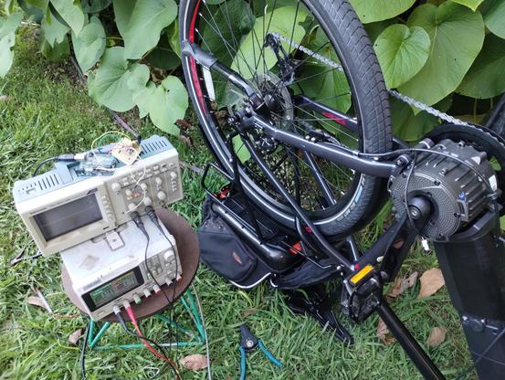
People replied a lot while I was sleeping. I''m not going to give the same response to everyone who was asking what its for, so I'll just say it here. I want to use an arduino to spoof the 0-5V analog throttle signal on this ebike i'm building.
As best I can tell, ebike throttle units put out an analog voltage without any kind of data signal, but somehow the e-bike knows the difference between a real throttle, and one made out of an arduino, or even made out of a bench power supply. It will only run when connected to an actual ebike throttle
I'm getting somewhere now. It's not giving full throttle but it is giving some throttle.
I had to hook up the throttle unit in parallel with the Arduino for the bike to accept inputs from the Arduino.
This might work out ok because i wanted to have a throttle lever and pedal assist anyway.
More testing to do still!
I briefly had it working without the throttle connected. I had put a 1.2K resistor between the positive and ground wires and that did it. The bike was under control of the Arduino. Then it just stopped working and hasn't worked since.
The Arduino still works, and the bike still works if I hook a regular throttle to it. Mysterious
Okay, it's working again. I don't know what's different, but it's working
Omg, not working again. This is kind of frustrating!
describe how it's supposed to work, at least in theory..
@MLE_online Does the motor controller need to see a voltage in the range that represents 0% throttle input when it powers up to unlock and start being receptive to throttle inputs?
@foundthefault undetermined. I have the Arduino programmed to supply that amount of voltage because I thought that might be the problem but there's an inconsistency here that I don't understand
@MLE_online What happens if you power it up with the normal throttle control connected and held at a partial throttle setting? Does that make it lock out?
@foundthefault great question. Something else to try
excellent point.
and is 0% throttle represented by +5V or 0V?
@MLE_online I'd guess that there's a bunch of conditions that trip it into thinking something's wrong. Hall effect throttles don't generally swing all the way from 0v to 5v. For example it might expect like 0.4v or whatever as a released throttle and a slight load across 5v and gnd to decide everything is ok to start.
I've only ever "faked" potentiometer throttles though so this is guessing. (digital pots are handy for this kind of nonsense)
@pimentoad Yea, real throttle swings between about .85V and 4.2V. I've programmed the arduino to have that same range, but who knows, maybe some of the PWM ripple is making it through the RC filter and upsetting the controller. It looks fine on the bench, but there might be something different once it's hooked to the bike. I may have to put my oscilloscope on it and see.
@MLE_online does it work with a pot directly? Sorry if you already answered that somewhere, but if it does a resistor ladder seems like the better answer.
I've never had great luck with trying to use pwm to fake stuff that was being monitored by some IC I didn't understand.
@pimentoad That is a good question. I have not tried that, but I will

@MLE_online what was resistor between v+ and ground supposed to do?
@MLE_online aha! I bet I know another answer!
Part 1: was the voltage TO the orig throttle (pot, I suppose) *slightly* less than 5V?
Part 2: did you ground the microcontroller to the "low" voltage lead of the 3 wires, or the "real" system ground?
What I think is going on: I think the signal your giving it is "out of range" like I said, the cart I have is picky, if the "value doesn't look right" it does a safety shutdown. You might find by limiting the max and min PWM levels, you find a "happy place"
I suggest starting it at 50%, and slowly dialing up/down to feel out the limits.
you got this! Were all counting on you!
:]
@RueNahcMohr It's a full 5V going to the original throttle. The original throttle is not a pot. It's a hall-effect thing.
I grounded the microcontroller to the black wire that is identified as ground.
I have already limited the max and min PWM levels so they match the voltage limits that the throttle outputs when it's at the bottom and top of its range
@MLE_online interesting, they must have a really curious "safe input" system in there.
I suppose you cant see the chip in the throttle, I suspect its a hall effect pot.
Does it look like this?
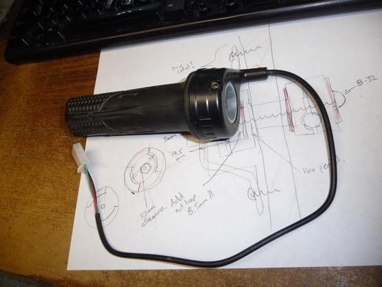
@RueNahcMohr It doesn't look like that, but it's probably similar inside. Does yours have a red, green, and black wire?
@RueNahcMohr So it's probably the same. These hall-effect throttles all seem interchangeable with each other. For testing purposes right now I'm using one from an escooter. The bike is perfectly happy with it
@MLE_online based on what I learned here, it must be ripple in your pwm freaking it out.
With the 1.2k resistor, its fine with the bench power supply signal?
'tomorrow' I know....
@RueNahcMohr the 1.2K resistor isn't between any two lines on the arduino. It's between the V+ and ground wires
@MLE_online I know.
scope this a second.... ( I know the filter might not be arranged right)
@RueNahcMohr I will try on saturday. I'm done with it for today and I have ceramics tomorrow
@MLE_online ok, its my understanding of what you have right now.
@RueNahcMohr the only thing you have wrong is that the 1.2K resistor is not connected to the positive 5V rail of the arduino
@MLE_online ! your powering the arduino from the throttle supply? oh, I wonder if thats the issue...
I'm going to come up with a crazy circuit you can try or not, but that I think might work.
:]
I don't suspect you will try it, I dont know why I'm driven to solve these puzzles..... oh right, core of personality.. ugh...
@RueNahcMohr I'm not. It's powered from a USB battery bank. That's why the positive side of the resistor isn't connected to the arduino. I've only tied the grounds and the signal lines together
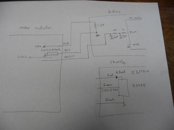
@MLE_online ah, so my diagram is good then!
@RueNahcMohr no it's not! You have the +5V of the motor controller and the arduino connected together
@MLE_online ah! miscomm. the inner box is the arduino, I didn't intend to say its + is common!
the outter box is meant as your arduino conditioning circuit.
heh, diagram fail Rue.
@MLE_online hmm, I think you have some CDS cells left over from a project that was light sensitive...
omg wait, is my brain cataloging what other people have too? ....
@MLE_online whats RC value are you using?
@RueNahcMohr It's a network with a 1k, a 10k, a 10uF and a 0.1uF
@MLE_online Is there anything that might help here? https://github.com/akomakom/arduino-throttle-smoother
@foundthefault Maybe? It looks like he's also using PWM output from the arduino to spoof the throttle signal, so I'm not sure if there's anything in there for me to try.
control a transistor with the potentiometer..
1. ardie -> potentiometer -> transistor -> motor control voltage
not
2. ardie -> potentiometer -> motor control voltage
#1 is probably how it's done inside the hall effect sensor chip. there is probably more than just hall effect sensor + amp etched on that silicon chip. Identify the hall chip if you can and grab the manufacturer's data sheet if possible to verify.
@MLE_online If you're still stuck, maybe try connecting a 100 ohm resistor between the sensor's voltage output and the throttle voltage input. Then you can connect a voltmeter to the 100 ohm resistor (not to GND, but both leads to the 2 sides of the resistor). If you see zero or near zero volts, then you know the throttle input really is a high impedance voltage input. But if you see "something else" maybe it'll shine some light onto this mysterious situation?
@PaulStoffregen I'll give that a try. Thanks!
@PaulStoffregen @MLE_online From the test so far, I suspect its watching the supply current to the throttle, and from the failure of the 1k attempt, I suspect its got a really narrow margin for error on the sense current.
@MLE_online that's wild and very curious
@smellsofbikes It is! I'm stumped at the moment


@MLE_online @smellsofbikes this beat me a while ago, too. I got as far as figuring out that my throttle was a hall effect type but didn't immediately understand why that was important and so moved on...
If you figure it out please let us know :)
If you figure it out please let us know :)
@Niall @smellsofbikes It shouldn't matter that it's hall effect, since it's ouputting a variable voltage between 1 and 4 VDC, but somehow it does matter. I see other people have undertaken projects using arduinos to create throttle signals on their ebikes, so this must be possible. I just don't see yet what I'm doing wrong
@MLE_online @smellsofbikes the controller normally has 3 wires: 5V; ground & signal. I presume you hooked your supply up to signal and ground? Does the controller also need to see some specific resistance between 5V and gnd so it 'knows' there's a throttle present?
@MLE_online @Niall @smellsofbikes Maybe the e-bike controller also needs a certain level of current with the voltage signal, or maybe it’s really 4-20mA (I know, I know it *should* be a high impedance input).
@MLE_online something about legal limits on how fast an evoke can go?
@MLE_online I'm having flashbacks...
https://rasterweb.net/raster/2017/05/29/controlling-the-controller-cheaply/
Controlling the Controller Cheaply
Hey, it's only been six months since my last post about motor controllers and the Power Racing Series so I guess it's time for an update! If you missed it, I'm working on a tiny electric vehicle that can serve as a reference for teams of beginners to build their own. In the last post [...]
@rasterweb Cool! It looks like to managed it.
Intuition tells me that 0-5v for a motor is not a sensible (purely analog) control voltage... not enough "steps" between 0 & 5. There must be more to the picture. I'de keep looking for it. See if there is not a digital signal being sent over the wire @ 5v.. +5 being a 1, and 0V being a zero.. you know the drill.
@Felis_Catus_Domesticus It's 0-5V lol. There is no digital signal. I promise you that!
what electronics are inside the throttle assembly?
@Felis_Catus_Domesticus It's a hall effect sensor and an amplifier
get the data sheet for the hall in question. study it. use the arduino in conjunction with that hall or some other. arduino outputs can't spoof what the hall sensor does with anything close to an acceptable degree of fineness for a throttle. Analog on/off at best from an ardie by itself
P.S. More than just hall sensor & amp, at least in this specific one. Data sheets are worth gold. The component in this diagram that you didn't mention is the reason the ardie + throttle + 5v works

arduino output voltages are very "bouncey" and not especially stable. better to use the ardie to control a dumb component that is stable at doing one simple job, in most cases.