Does anyone on here know if the capacitor-resistor combo attached to a pwm output pin of an Arduino gives a decent analog output?
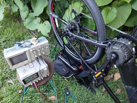
People replied a lot while I was sleeping. I''m not going to give the same response to everyone who was asking what its for, so I'll just say it here. I want to use an arduino to spoof the 0-5V analog throttle signal on this ebike i'm building.
As best I can tell, ebike throttle units put out an analog voltage without any kind of data signal, but somehow the e-bike knows the difference between a real throttle, and one made out of an arduino, or even made out of a bench power supply. It will only run when connected to an actual ebike throttle
I'm getting somewhere now. It's not giving full throttle but it is giving some throttle.
I had to hook up the throttle unit in parallel with the Arduino for the bike to accept inputs from the Arduino.
This might work out ok because i wanted to have a throttle lever and pedal assist anyway.
More testing to do still!
I briefly had it working without the throttle connected. I had put a 1.2K resistor between the positive and ground wires and that did it. The bike was under control of the Arduino. Then it just stopped working and hasn't worked since.
The Arduino still works, and the bike still works if I hook a regular throttle to it. Mysterious
Okay, it's working again. I don't know what's different, but it's working
Omg, not working again. This is kind of frustrating!
@MLE_online I'd guess that there's a bunch of conditions that trip it into thinking something's wrong. Hall effect throttles don't generally swing all the way from 0v to 5v. For example it might expect like 0.4v or whatever as a released throttle and a slight load across 5v and gnd to decide everything is ok to start.
I've only ever "faked" potentiometer throttles though so this is guessing. (digital pots are handy for this kind of nonsense)
@pimentoad Yea, real throttle swings between about .85V and 4.2V. I've programmed the arduino to have that same range, but who knows, maybe some of the PWM ripple is making it through the RC filter and upsetting the controller. It looks fine on the bench, but there might be something different once it's hooked to the bike. I may have to put my oscilloscope on it and see.
@MLE_online does it work with a pot directly? Sorry if you already answered that somewhere, but if it does a resistor ladder seems like the better answer.
I've never had great luck with trying to use pwm to fake stuff that was being monitored by some IC I didn't understand.
@pimentoad That is a good question. I have not tried that, but I will