Does anyone on here know if the capacitor-resistor combo attached to a pwm output pin of an Arduino gives a decent analog output?
People replied a lot while I was sleeping. I''m not going to give the same response to everyone who was asking what its for, so I'll just say it here. I want to use an arduino to spoof the 0-5V analog throttle signal on this ebike i'm building.
As best I can tell, ebike throttle units put out an analog voltage without any kind of data signal, but somehow the e-bike knows the difference between a real throttle, and one made out of an arduino, or even made out of a bench power supply. It will only run when connected to an actual ebike throttle
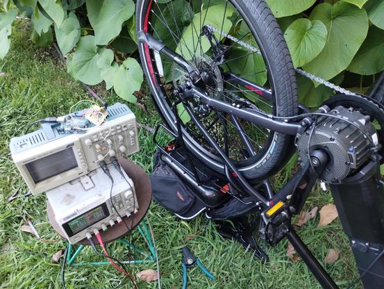
I'm getting somewhere now. It's not giving full throttle but it is giving some throttle.
I had to hook up the throttle unit in parallel with the Arduino for the bike to accept inputs from the Arduino.
This might work out ok because i wanted to have a throttle lever and pedal assist anyway.
More testing to do still!
@MLE_online If you're still stuck, maybe try connecting a 100 ohm resistor between the sensor's voltage output and the throttle voltage input. Then you can connect a voltmeter to the 100 ohm resistor (not to GND, but both leads to the 2 sides of the resistor). If you see zero or near zero volts, then you know the throttle input really is a high impedance voltage input. But if you see "something else" maybe it'll shine some light onto this mysterious situation?
@PaulStoffregen I'll give that a try. Thanks!
@PaulStoffregen @MLE_online From the test so far, I suspect its watching the supply current to the throttle, and from the failure of the 1k attempt, I suspect its got a really narrow margin for error on the sense current.