Does anyone on here know if the capacitor-resistor combo attached to a pwm output pin of an Arduino gives a decent analog output?
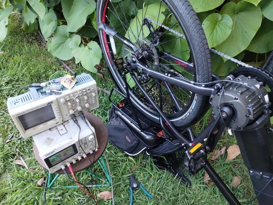
People replied a lot while I was sleeping. I''m not going to give the same response to everyone who was asking what its for, so I'll just say it here. I want to use an arduino to spoof the 0-5V analog throttle signal on this ebike i'm building.
As best I can tell, ebike throttle units put out an analog voltage without any kind of data signal, but somehow the e-bike knows the difference between a real throttle, and one made out of an arduino, or even made out of a bench power supply. It will only run when connected to an actual ebike throttle
Intuition tells me that 0-5v for a motor is not a sensible (purely analog) control voltage... not enough "steps" between 0 & 5. There must be more to the picture. I'de keep looking for it. See if there is not a digital signal being sent over the wire @ 5v.. +5 being a 1, and 0V being a zero.. you know the drill.
@Felis_Catus_Domesticus It's 0-5V lol. There is no digital signal. I promise you that!
what electronics are inside the throttle assembly?
@Felis_Catus_Domesticus It's a hall effect sensor and an amplifier
get the data sheet for the hall in question. study it. use the arduino in conjunction with that hall or some other. arduino outputs can't spoof what the hall sensor does with anything close to an acceptable degree of fineness for a throttle. Analog on/off at best from an ardie by itself
P.S. More than just hall sensor & amp, at least in this specific one. Data sheets are worth gold. The component in this diagram that you didn't mention is the reason the ardie + throttle + 5v works

arduino output voltages are very "bouncey" and not especially stable. better to use the ardie to control a dumb component that is stable at doing one simple job, in most cases.