Does anyone on here know if the capacitor-resistor combo attached to a pwm output pin of an Arduino gives a decent analog output?
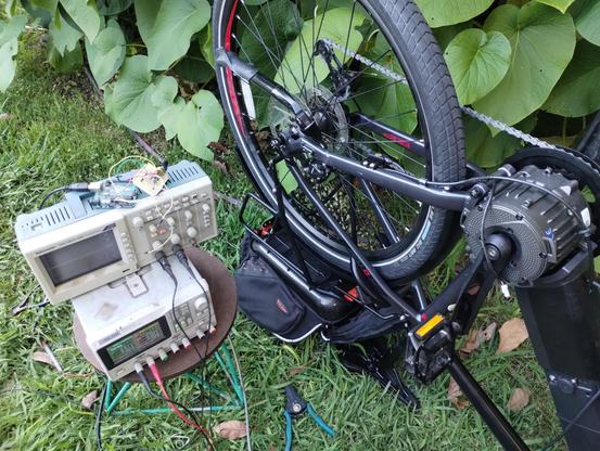
People replied a lot while I was sleeping. I''m not going to give the same response to everyone who was asking what its for, so I'll just say it here. I want to use an arduino to spoof the 0-5V analog throttle signal on this ebike i'm building.
As best I can tell, ebike throttle units put out an analog voltage without any kind of data signal, but somehow the e-bike knows the difference between a real throttle, and one made out of an arduino, or even made out of a bench power supply. It will only run when connected to an actual ebike throttle
I'm getting somewhere now. It's not giving full throttle but it is giving some throttle.
I had to hook up the throttle unit in parallel with the Arduino for the bike to accept inputs from the Arduino.
This might work out ok because i wanted to have a throttle lever and pedal assist anyway.
More testing to do still!
I briefly had it working without the throttle connected. I had put a 1.2K resistor between the positive and ground wires and that did it. The bike was under control of the Arduino. Then it just stopped working and hasn't worked since.
The Arduino still works, and the bike still works if I hook a regular throttle to it. Mysterious
Okay, it's working again. I don't know what's different, but it's working
Omg, not working again. This is kind of frustrating!
describe how it's supposed to work, at least in theory..
@MLE_online Does the motor controller need to see a voltage in the range that represents 0% throttle input when it powers up to unlock and start being receptive to throttle inputs?
@foundthefault undetermined. I have the Arduino programmed to supply that amount of voltage because I thought that might be the problem but there's an inconsistency here that I don't understand
@MLE_online What happens if you power it up with the normal throttle control connected and held at a partial throttle setting? Does that make it lock out?

@MLE_online whats RC value are you using?
@RueNahcMohr It's a network with a 1k, a 10k, a 10uF and a 0.1uF
@MLE_online Is there anything that might help here? https://github.com/akomakom/arduino-throttle-smoother
@foundthefault Maybe? It looks like he's also using PWM output from the arduino to spoof the throttle signal, so I'm not sure if there's anything in there for me to try.
control a transistor with the potentiometer..
1. ardie -> potentiometer -> transistor -> motor control voltage
not
2. ardie -> potentiometer -> motor control voltage
#1 is probably how it's done inside the hall effect sensor chip. there is probably more than just hall effect sensor + amp etched on that silicon chip. Identify the hall chip if you can and grab the manufacturer's data sheet if possible to verify.
@MLE_online If you're still stuck, maybe try connecting a 100 ohm resistor between the sensor's voltage output and the throttle voltage input. Then you can connect a voltmeter to the 100 ohm resistor (not to GND, but both leads to the 2 sides of the resistor). If you see zero or near zero volts, then you know the throttle input really is a high impedance voltage input. But if you see "something else" maybe it'll shine some light onto this mysterious situation?
@PaulStoffregen I'll give that a try. Thanks!
@PaulStoffregen @MLE_online From the test so far, I suspect its watching the supply current to the throttle, and from the failure of the 1k attempt, I suspect its got a really narrow margin for error on the sense current.
@MLE_online that's wild and very curious
@smellsofbikes It is! I'm stumped at the moment


@MLE_online @smellsofbikes this beat me a while ago, too. I got as far as figuring out that my throttle was a hall effect type but didn't immediately understand why that was important and so moved on...
If you figure it out please let us know :)
If you figure it out please let us know :)
@Niall @smellsofbikes It shouldn't matter that it's hall effect, since it's ouputting a variable voltage between 1 and 4 VDC, but somehow it does matter. I see other people have undertaken projects using arduinos to create throttle signals on their ebikes, so this must be possible. I just don't see yet what I'm doing wrong
@MLE_online @smellsofbikes the controller normally has 3 wires: 5V; ground & signal. I presume you hooked your supply up to signal and ground? Does the controller also need to see some specific resistance between 5V and gnd so it 'knows' there's a throttle present?
@MLE_online something about legal limits on how fast an evoke can go?
@MLE_online for throttle? yeah homie you could throw just about any RC combination at a slow-moving signal like that. If it's too laggy, lower the RC constant.
@MLE_online
Might I suggest a dead-man switch of some sort?
Might I suggest a dead-man switch of some sort?
@JohnS_AZ The dead man switch is when I fly off
@MLE_online @JohnS_AZ What's the airspeed velocity of an unladen Emily?
@MLE_online depends on the purpose... If you want is to be smooth it cant change fast.
@RueNahcMohr how fast or slow?
@MLE_online @RueNahcMohr what arduino do you have? They have different PWM speeds. And what is your acceptable ripple in your output?
Slowest pwm is 490hz. If you filter that with a 1k resistor and a 10uf capacitor, that’s a cutoff of about 16hz. So you could have a control signal of about that. It would have a ripple of about [edit: 0.25] volts on the output
Edit: I accidentally ran the calculation at the wrong PWM speed. The slower speed gives you .25 volts ripple, the faster gives you 0.12v
@MLE_online @RueNahcMohr additional info: you can software bit bang a faster pwm, there are arduino libraries
Also, you can use this calculator for PWM. It has been around for decades and I use it all of the time. Just plug in the pwm frequency, and the resistor and capacitor values and it will come back with cutoff frequency, and output ripple, and even graph it over time
@MLE_online thats set by the RC combination you use. Are you gonna tell what you want to use it for?
If the pwm is at 100kHz and you are trying to generate a sub 100hz tone, it might be fine. If you want full bandwidth audio to 20kHz, nope.
https://www.allaboutcircuits.com/technical-articles/low-pass-filter-a-pwm-signal-into-an-analog-voltage/
additionally, if you need steady more than resolution, an R-2R DAC is easy to make.

@MLE_online Low pass filtering PWM to get analog voltage always comes with 3 unavoidable problems. Whether you consider the result "decent" depends on how low your expectations are.
@MLE_online Problem 1 is output impedance. The signal is "weak" because of the resistor. If you will drive something very high impedance like an opamp input, maybe it's a non-issue. If you want a strong signal, you'll need to add an opamp or other way to buffer the output.
@MLE_online Problem 2 is noise on the power supply couples to your signal. With a proper DAC you would look for a PSRR (Power Supply Rejection Ratio) spec or graph to give an idea of how much noise can couple from power to signal. You might power the DAC with separate "clean" power. DACs use a reference voltage too, which is very stable. With low pass filtered PWM, any lower frequency noise on your "digital" power supply goes straight into your signal. Pretty much the worst PSRR scenario!
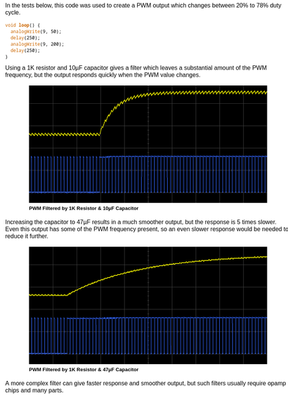
@MLE_online and of course Problem 3 is trade off between slow response versus some of the PWM frequency remaining. Here's documentation for Teensy to give a quick visual idea, but it applies to Arduino or any other PWM output.
@PaulStoffregen @MLE_online Very interesting! And if you chose to do PWM anyhow, maybe even for audio: What would best practices? Output buffer, ...?
@mixal @PaulStoffregen @MLE_online PWM is not terrible and when combined with high/low-side switching with power transistors can be used to very efficiently provide high-power analog signals to inductive or capacitive loads (look up Class D power amplifiers). I would pick a PWM frequency much higher than the signal bandwidth and do some proper filter calculations/filtering however. The resolution of the duty cycle in your microcontroller becomes (an upper bound on) your sample resolution
@mixal @MLE_online Normally the best practice is to use PWM to directly drive your lights or motor or loudspeaker or whatever other physical thing ultimately matters, which can naturally "ignore" the PWM's high carrier frequency. Perhaps use minimal filtering like ferrite beads, only for the sake of limiting radio noise you spew into the world. For audio driving a speaker, usually use a dedicated power supply to minimize the PSRR problem.
@MLE_online I'm gonna some assumptions and say hell yes.
Whatcha cooking up this time?
@ArchiteuthisFlux I have an idea I want to try on this new ebike project. The motor controllers for these things have nice throttle response, but the pedal assist sensor response is just on-off. I was thinking I would try using an arduino to read the speed the pedals are turning from the pedal assist sensor and then generate a 0-5V throttle signal.
I want to see if I can make it so the bike provides an amount of throttle that corresponds to how much pedaling you're doing
@MLE_online Oh sick. I always thought it was weird that ebikes didn't work that way by default.
Like @stargirl said, a throttle signal like that is the least demanding analog output ever and could be done on pure vibes. I would put a little pot on it that you multiply with the pedal signal in the analogWrite() and then just twiddle it while riding until it feels right.
Because doing math is for nerds.
@ArchiteuthisFlux @stargirl I was thinking exactly something like that!
I don't understand why they don't work that way. They clearly can provide a variable amount of throttle, but someone at some point decided that the pedal assist shouldn't work like that and then every factory in China that makes these controllers did it the exact same way.
@MLE_online @stargirl I wonder if that has something to do with the ridiculous number of laws around ebikes in some places.
"God forbid people just move the throttle and it goes, they must also be perfomatively moving their feet in circles for some reason."
@ArchiteuthisFlux @stargirl maybe? just pretend to be doing something with your feet and you get to go full speed
@MLE_online You'll get lots of answers since it depends on the application. However, I'd simply say no.
https://amzn.to/47B1jyf
https://amzn.to/47B1jyf
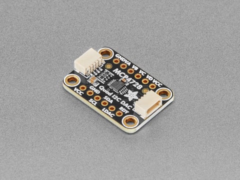
Amazon.com: WWZMDiB 2 Pcs MCP4725 DAC Converter Module 12-bit I2C IIC Compatible with for Arduino Raspberry Pi ESP32 STM Digital to Analog Converter Board : Electronics
Amazon.com: WWZMDiB 2 Pcs MCP4725 DAC Converter Module 12-bit I2C IIC Compatible with for Arduino Raspberry Pi ESP32 STM Digital to Analog Converter Board : Electronics
@MLE_online For some value of decent, sure. This is a very common way of doing a crude DAC. As long as the other side isn’t sensitive to the switching noise, and you don’t need to switch it any faster than the filter will let you, you’ll be fine.
@MLE_online I've used it for various terrible purposes, including workable audio.
@MLE_online Depends on your use case. Here's a good introduction: https://www.allaboutcircuits.com/technical-articles/turn-your-pwm-into-a-dac/