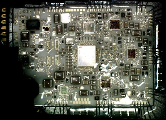
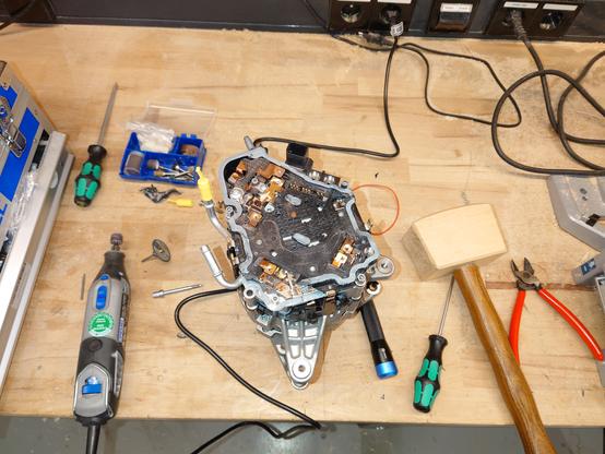
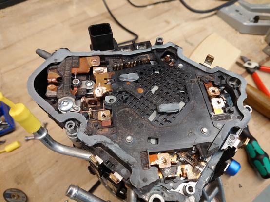
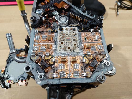
Bought a #Mercedes #48V #MHEV #startergenerator for #reverseengineering.
The specs are impressive, especially for the price point of a few hundred euros.

- 48V / ~200A
- 12.5 kW peak
- 165 Nm peak

The main difficulty lies in finding out the #CAN commands for initialization and control.

I don't have access to a Mercedes E200 EQ Boost (or similar), so "just sniffing" is out.
Maybe somebody could help me with that tho? ^^'

#CANhacking #carhacking #BSG

After much digging I at least found the pinout in some Mercedes shop software.

But unsurprisingly the #startergenerator didn't send any messages on its own on the #CAN bus when hooked up to 12V.
It did draw 11 mA tho, so at least the pinout seems correct and the controller appears awake.

Trying to send some #CAN messages to the #startergenerator didn't prove successful either.
I'm not well versed in CAN, but the dongle just kept trying to send the single message on repeat.
So I guess it didn't receive a CAN ACK?
Afaik, all transceivers in a bus should ACK a frame, no matter if they're addressed or not.

Not sure why it didn't work. Maybe I was on the wrong baud rate or this device behaves weirdly and only sends ACKs after getting a magic message?

#CANhacking #carhacking

Another mystery I couldn't solve yet: Which #automotive #connector is this?

After some research, it looks pretty similar to some variant of the AMP MCP series, but I could not find an exact match.

Dimensions:
Outline WxH: 21.35 x 16.5 mm
Depth: 21mm
Centerline pitch: roughly 4mm

Found the connector after much searching!
It's a TE "MCON 1.2".
But it's unavailable everywhere, of course ^^"

Was quite hard to find, because that series is normally only available in single row or something along those lines.

And most searches only brought up the AMP MCP1.5K REC HSG, which would almost fit too in most of the important dimensions, but the outline is different.

Got out the #startergenerator again today.
But (destructively) removing the back cover of the #BSG revealed even less than I had feared...

Just a big welded(!) copper distribution plate and more plastic and silicon.

Only a hint of ceramic PCB can be seen through a tiny little hole, that's it.

Going any further than that really needs some effort and would very likely lead to damage of the power electronics, so I'll probably stick to the #CAN fuzzing / information digging approach for now...

Fuck yeah! Finally got _any_ #CAN output out of the #MHEV #BSG!

I'm glad it actually was something stupid ^^
I did test it with and without 48V connected in the past, but apparently I neglected to connect the two GNDs (power and signal GND) together.
I did now and the behaviour changed completely.
It now draws 250mA instead of 11, goes into sleep (0mA) after 5s of no CAN activity and most importantly, spews out a bunch of messages after detecting any CAN activity, wohoo \o/

#CANHacking

Another minor stumbling block was that #CAN H/L were swapped, compared to what I had gathered from the official(?) wiring schematics. (But everything else was correct).
Idk why, but I triple checked it again and they're definitely the wrong way around in the documentation. Interesting :D

Now I can finally get to the fun part of actually trying to send the #BSG all the many many messages it wants to see and figuring out what values it needs, to do anything at all ^^

Update time:
At the end of December I implemented most of the messages the #startergenerator wants to see.
I knew I got it right enough because the 7 DTC codes it was previously spitting out shrank to just 1. The ones that went away were something like "communication failure power train controller", but the one remaining DTC was a bit disheartening...

"P143468: Imob_E_LOCKED - The driving authorization has not been released."

It looks like the #BSG is part of the #DAS (drive authorization system). Kinda makes sense, since it also acts as a starter motor, but it means that I'm now up against the #Mercedes #FBS4 DAS.
I really don't want to reverse-engineer a car immobilization system though. For several reasons.
But I took a quick look anyway.
Using a #UDS database, I did a little poking against the FBS4 methods like personalization or activation, but the BSG only sends some cryptic CAN messages to the EIS ECU (ignition switch module). And since I obviously don't have an EIS, the UDS calls just fail.
I've figured out the message structure of the messages between the BSG and the EIS for the most part, but without knowing what they're even negotiating, it's pretty much a dead end, I'm afraid.
So in January, I tried to dump the firmware, with moderate confidence of success.
In the #UDS database, there obviously wasn't any method defined for downloading the firmware, only uploading.
But I played around with the default downloading commands anyways, although with no success.
So I tried other methods of obtaining the firmware:
There is the CAN #XCP protocol (Universal Measurement and Calibration Protocol) which does pretty much what it sounds like. But it's usually locked down for production.
Fortunately, this was not the case for the BSG :D
I had to hack together my own XCP dump script and it took about 20 minutes to dump the first contiguous memory segment before the BSG reset the session. (CAN is slow ^^")
Now I had exactly 2 MiB worth of some kind of data, maybe/probably the flash contents.
Time to take a closer look at the dump.
It has a few distinct data sections with empty sections in between.
There are some interesting strings in the dump, but nothing I can immediately make sense of.
But what worries me the most is that it doesn't seem to be just machine code.
At least it's not encrypted, I think, the entropy is too low for that.

But it looks like some kind of structured data (see attached image, a normal firmware doesn't look like this, ime). Almost looks like many structs after each other, but idk. Maybe some weird #AUTOSAR thingy?
I also threw #Ghidra against the dump with some of the suspected architectures (#MCP5xxx, #PowerPC, #Tricore), but none returned any plausible looking instructions.

If anyone has an idea how the firmware of a Mercedes / Bosch ECU from ~2016 could be structured, hmu. 

I also found a firmware update file in the depths of the internet that would write to the memory area 0x060000-0x1FFFFF, so it seems I definitely dumped the firmware. But I haven't found a way to extract a .SMR-F file to compare the contents yet.
I'm pretty stumped on how to proceed with the flash dump...
Since I didn't see a reasonable way to proceed, the project lay dormant for a few months.
But last week, I got too curious, so I tore open the control electronics, hoping to find out the MCU type that way.
It took quite some (careful) dremeling, chiselling and levering. I got it apart without damage, but to reassemble it I'd have to reconnect about 20 copper busbar connections.
What was revealed when I broke off the last plastic cover was not quite unexpected, but still a sight to behold!
I put the electronics under a microscope to hopefully see some die markings.
The main MCU is from ST with the silicon die marking #FL62X2 and has 172 bond wires attached. Of course searching for that marking yields nothing.
But the fact that it is made by ST should narrow it down considerably. As far as I know, the only automotive-grade MCU made by ST is the #SPC5 (PowerPC, like the MPC5xxx).
But of course it could be something completely custom, who knows.

So now I have a lot of loose threads to follow, but none of them seems immediately promising:
1) Build own 5-phase motor controller
2) Gain some key CAN logs to reverse engineer the #FBS4 personalization and activation procedure
3) Find a way to read the firmware dump to:
a) rev-eng FBS4
b) understand just enough of FBS4 to patch it out
4) ???

If somebody would be interested in helping me solve that firmware puzzle, I'd be very happy!

I got a bit more progress in on the #startergenerator.
Massive thanks to @SDRHoernchen for finding the exact ST SPC5 from the die marking and @blazra for the VLE hint.
(And ST for not putting the reference manual behind a NDA)

With that information I could start actually #reverseengineering the firmware in #Ghidra.

I already found some CAN handling.

The decompiler really struggles with the r2/r13 SDA/ToC registers and almost never resolves them to the actual memory address accesses though :/

In the end of June, I found out how to fix that pesky r2/r13 register problem.
I had to mark r2 and r13 as "unaffected" in a few "ppc_64*.cspec" files in the #Ghidra Processors/PowerPC/data/languages folder.

Then, most memory accesses got resolved correctly.
Probably not the best solution, but it worked.

And I could finally dive head first into the actual reverse engineering.

I spent many dozens of hours losing track of time in #Ghidra (I swear, it's worse than #Factorio)

Until I had figured out the #CAN message handling, signal parsing and where and when which #DTC codes get set.
With that knowledge I could figure out, slowly but surely, what the #startergenerator needs to run.
Even #FBS4 was pretty trivial to circumvent (a single 1 written to the right memory location via #XCP)

And after implementing the ~25 CAN messages in my STM32 code I finally got this today:

There's still a lot left to do.
I need to implement the #XCP stuff into the STM32 firmware, so it can run the #startergenerator stand-alone.
Stuff like:
- Checking the firmware version on the ECU, so it doesn't poke the wrong memory address
- Reading and parsing the status of the motor
- And actually controlling the motor properly instead of just sending it a hardcoded 1 Nm torque request :D

And then also cleaning it up enough, documenting and testing it thoroughly, so it can be published.

We also did a max RPM test of the #startergenerator using one of @patagona's rescued Pylontech batteries, because the 20A of my 1kW lab PSU weren't enough :D

I set the torque limit to 0.7 Nm (out of 55), no RPM limit and let it rip :D
It reached a peak of 43A (~2kW) at the end of the acceleration, settled at 25A (~1.2kW) and reached a peak RPM of 13400.

It was a bit scary tbh :D
(Not sure if the video accurately captured the sound it made)

(Pylontech thread: https://chaos.social/@patagona/113149877881417810 )

patagona (@[email protected])

Attached: 1 image Heute bei "Kleinanzeigen-Unfälle mit patagona": 3x 2.4kWh 19" LiFePo4-Akkumodule für unter 200€ Der Catch: die Dinger sind nem Wasserschaden zum Opfer gefallen. (Thread) #LiFePo4 #Solar

chaos.social

The general control loop is also pretty impressive, the engineers at #Bosch SEG definitely did their job well.

The lowest limit I can set is 6 RPM and it runs buttery smooth.

And it has insane amounts of torque. If you hold the pulley really tightly, it slips out of most strong hands at around 6-7 Nm (as reported via the CAN status messages).

This will be really fun once put into some small vehicle :D

(It can also recuperate really well, but can't run in reverse at all)

#startergenerator

Today, I've built a "temporary" test stand, so I can hopefully test the (thermal) performance of the #startergenerator in the coming days.

It was a welcome excuse to finally dabble in some metalworking again :D

Also, those belt tensioners really need quite some force.

Finally got to doing some dyno runs with the #startergenerator this week.

As I'm able to vary many factors (target drive torque, generating torque, RPM and time), I tested many variations.

tl;dr: They definitely deliver on their 12.5 kW promise, but the stator gets hot quickly, especially at low RPMs and high torque.
I couldn't test the full 55 Nm, only up to 36.6 Nm, as that's the generating limit.

I'm still amazed by the engineering of those things. So much data and protections :D

I've also built a Grafana dashboard for this test setup.
Each #startergenerator is connected to a STM32F072 via CAN which are then connected to the PC via USB serial.
A script then forwards control commands to the STM32s and also receives the telemetry data and publishes them to an InfluxDB.

Here you can see the data of the first video and also a more zoomed out view of the test runs with increasing torque target and slow RPM ramp up.

Because they report voltage, current, torque and RPM (and I trust those values reasonably), I'm able to calculate the kinetic power and electrical power. The difference between those two values should approximate the efficiency of the #startergenerator.
So I quickly threw together a plot of the efficiencies at various RPM and torque levels. Both for the driving and generating mode.
I honestly expected a bit more, but I guess they are more optimized for torque and other factors :D

Maybe I'll test the thermal performance some more, if I'm bored. I'd like to find out which factors influence the heat loss the most. It's not only torque or phase current, it seems a bit more complex.

But from all the available data at hand: I'm pretty sure they are suited well for project #Torquee (an electric go-kart I'm currently building).
I mean, you can't pull that torque in a vehicle for long times anyways, at some point you're either at v_max or need to decelerate for the next turn :D

Also have a bonus video of the #startergenerator spinning up to 4500 RPM under 20 Nm of load without ramp-up.

Sooo. Before I procrastinate it any longer (because my perfectionism claims that it's not finished enough), I've decided to finally publish the current, unfinished state of the firmware and some accompanying documentation for the #startergenerator

https://github.com/RainbowLabsDE/BSG-Driver

I hope it helps ;)

GitHub - RainbowLabsDE/BSG-Driver: A WIP firmware to control a 48V belted starter generator (BSG) out of a Mercedes MHEV

A WIP firmware to control a 48V belted starter generator (BSG) out of a Mercedes MHEV - RainbowLabsDE/BSG-Driver

GitHub
@LeoDJ That looks like a lot of fun!
@LeoDJ Nice Project and impressive Setup
@LeoDJ Woah, very cool project! And congrats on getting it to work!
Id love to see you get this working. I found out that the starter on my small turbine engine is toast and this would make a great replacement.

@LeoDJ Fantastic! Doubly impressive that you got it turning from analysing it in isolation.

Resisting the urge to start a motorbike project now 😅

@LeoDJ the coil whining 🙉
@LeoDJ that's awesome work and really impressive reverse engineering 👏
Are the details collected somewhere e.g. on GitHub?
On openinverter.org there's some interest and it would fit on the Wiki as well - similar to the Mitsubishi Outlander PHEV front and rear motors, which also just need CAN messages.

@marcaurelevers
Not yet, though I'm planning to publish it soon-ish.
I want to make sure it works reliably first and do a proper write-up for it.

I also had a thread there, but didn't update it (yet) ^^"
https://openinverter.org/forum/viewtopic.php?t=4402

Mercedes Benz 48V MHEV BSG - Help needed - openinverter forum

@LeoDJ any interest in joining Damien's Discord server? I can ask to invite you, lots of reverse engineering going on there.
Hi, curious if you got any further with this. I have an application that I think this would work nicely for. I have a smallish (150HP) Garrett gas turbine that this would make a great starter-generator for. I have a 12krpm shaft output that could tie directly into the alternator and even turns the right direction. Then turn this into the least efficient hybrid go-cart ever.
@LeoDJ Did you ever try to use it as a generator? I happened to stumble across a half-broken gasoline power generator, and am wondering if I should try to put one of these into it.
The starter could also act as a starter for the motor, giving it a super fancy extra feature...
@manawyrm
I didn't get to testing it with mechanical load yet, but it can definitely regen brake with some torque according to how quick it stops, if I set the negative torque target to something other than 0 :D
(And the spike in lab bench PSU voltage 😬)
@manawyrm
(But it has a maximum voltage limit that it targets, so it doesn't even blow up the PSU iirc.
It just keeps it at ~54V until its spun down.
Still didn't try it again after that :D)
@LeoDJ That sounds pretty damn cool, I have those same Pylontech batteries as pata once repaired... I wonder if they'd pair up with that thing well in a gas generator with direct DC-power *hmmm* :3
@LeoDJ hmm I wonder what the max RPM in the car will be, probably not too far off your max? Would need to figure out some dimensions of the pulleys to get the exact number
@nicoduck
The ratio is pretty exactly 1:3.
The RPM value it reports via CAN is 3x slower than it actually spins, which means it reports RPM and torque as "engine values" not "starter generator values".
So it can support the combustion engine up to around 4000 RPM (after that the reported available torque drops off)
@LeoDJ That's nothing short of amazing!
Congrats, outstanding work! :3

@LeoDJ  That is some seriously impressive reverse engineering! Well done!

I really didn't think it was really feasible without building half a car. Hats off!! 👏

@LeoDJ amazing! I am in awe at your persistence with this
@LeoDJ was not expecting to scroll up from this and see a car starter
@LeoDJ Many projects with SPC5s use just the VLE instructions not the classic PowerPC ones - did you try to find those?
@LeoDJ You could maybe confirm that it is an SPC5 by finding the boot header. It starts with 0x5A or 0xA5 and must be present at one of the specific addresses. For example for SPC57 (https://www.st.com/resource/en/reference_manual/rm0408-spc574kx--32bit-power-architecture-based-mcu-for-automotive-powertrain-applications-stmicroelectronics.pdf):

@blazra Ooohh, yeah, "VLE" seems to have been the magic word.
That does seem to fit. It looks to be machine code after all, at first glance.

I'll have a deeper look at SPC5 and how it works (like the boot header you'Ve mentioned), maybe I'll figure something out.

Thank you so much already!

Ukraine wants only peace. Deny the war.

@SDRHoernchen
Oh wow, great find!
Well that proves it then, thanks :)

Just out of curiosity, how did you manage to find that? I used many search engines but none managed to find that PDF ^^

(Also hooray for Munro. I also follow their YT channel. They appear to be one of the few freely accessible sources of good technical information in the automotive scene ^^" )

@LeoDJ I remember reading that 10 years ago so it was just a matter of using the web archive to find the file names of all the xdevs munro report pdfs (archived dir index) and checking those....

@LeoDJ Those are some nice pictures! 😻

Does anything on the device look like it might have a JTAG interface? If it really was an e200 core, you might have a bit of a shot there...

@manawyrm Thanks ^w^
Hmm, nothing that immediately sprung into my eye.
Sadly the ceramic PCB appears to have multiple layers and so it's pretty hard to trace anything.
The bond pads along the edge of the PCB could be anything...

But maybe I overlooked something. Here's an un-annotated version of the stitched microscope image:

@LeoDJ okay, so i wrote a parallel eeprom dumper script a few weeks ago, and i got a similar output. turns out i messed up one of the pins and i wasn't incrementing bits properly (instead of having 15 address lines I had 14, and I was missing the first bit)

obviously this isn't exactly this, but this looks SO similar
@LeoDJ ah nvm, you got some strings in there, too

... have you tried binwalk? maybe it's just partially encoded with some aes/xor

@domi @LeoDJ
why would AES have the period of 4 bytes tho?

My guess is that it's some ladder logic compiled down to some bytecode which is then executed by a small interpreter

@wolf480pl @domi
Yeah, exactly that's my fear as well.
And as long as I don't know the interpreter, it's pretty much useless gibberish to me, I guess...
@wolf480pl @LeoDJ other parts have a period of 10 bytes, with one byte changing each turn. so I suppose you may be right
@domi Yup. Binwalk didn't find anything meaningful, except two "CRC32 polynomial table, big endian".
cpu_rec and WiiBin also didn't turn up anything conclusive.
@LeoDJ I just did a very quick search but found this based on the strings on your screenshot: https://github.com/Depthkernelcore/Arccore/blob/master/memory/Fee/Fee.c
If this Fee module is the same referenced by the strings the binary structure might come from wear leveling writing updates of the data objects one after the other into flash.
Arccore/memory/Fee/Fee.c at master · Depthkernelcore/Arccore

Contribute to Depthkernelcore/Arccore development by creating an account on GitHub.

GitHub