
Why, #gtkwave, why? What don't you like? You see the values from the sim #fpga and you correctly know that they aren't 0. And you seem to know it's a string of bits. What does that leave? Why are you angry/confused by 1s and only in this variable?
@remi Aha! I really have to stop thinking serially.
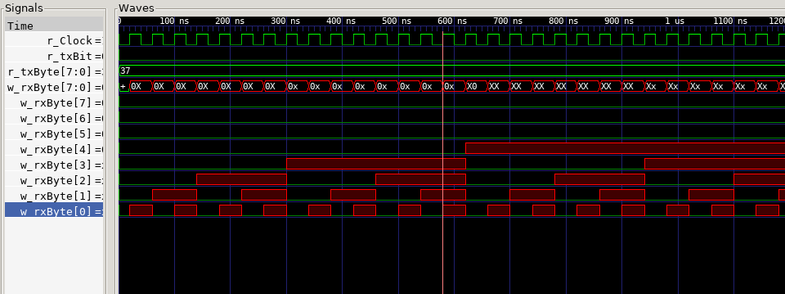
I "initialized the variable" in the testbench and then the actual module was setting the value. With the clue about multiple drivers, I just dropped the "initialization" and it's allll green.
@davidr
I'd draw out the circuit for a few simple things and the equivalent hdl. Maybe do a rising edge detector, an accumulator and a mux.
Don't ever do anything outside of a clocked process. There are ~zero real cases where that is useful.
Every signal should be assigned in only one process.
Every conditional case should assign every output unless you want a register.
Code up violations of these rules and draw the resulting circuit to see why they are good rules.
@remi
@davidr @poleguy Well if you know what a logic gate does, and if you know what a flip-flop does, you're like... 95% of the way there! 😆
Remember that these HDL languages (whatever flavor you like) are MODELING languages. Remember back when I said, in simulation you can do whatever you like? Well the flipside is that in RTL (register transfer level -- basically "going to become real") you can't. It may be useful to find some examples that connect cod e to schematic. 1/2
@remi @poleguy I really like this idea of real-izing a design. Except not a schematic--I have to be concrete.
I'll build some things side-by-side and see what clicks. Logic gates, flip-flops, Ben Eater's 6502 PS2 keyboard interface...
I have to stick to the tutorials long enough to get some basic syntax and building/debugging techniques. Then I'll branch out.
@davidr @poleguy
I realize this may be throwing you a little in the deep end, but if you go slowly, you should be able to glean some general patterns. This document is Intel's HDL recommended coding guidelines. It ought to have most of the basic semantic models that translate into real logic gate and register structures (and probably more, but just take it slow.)
