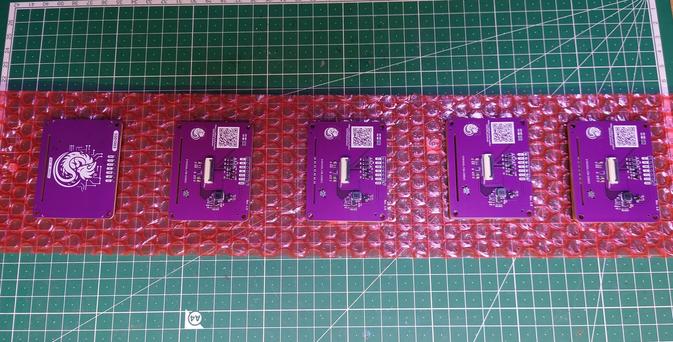
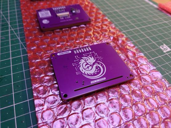
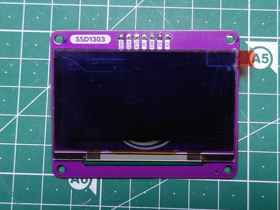
Got a bit carried away designing a breakout board for some old #SSD1303 #OLED displays I got from a friend.
- Built the (shitposty) #USB2Speakon adapter
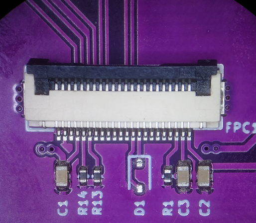
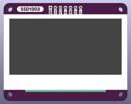
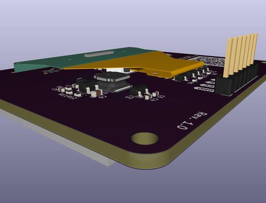
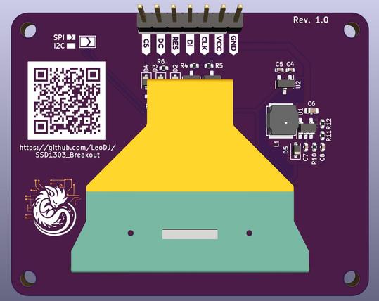
- Designed a new revision of the #SSD1303 breakout PCB
- Developed a small ESP-NOW telemetry and logging framework for a model rocket #jfzhn project
- Finished reverse engineering the #startergenerator. It spins now! \o/
- Built #TheLAEMPAN together with @techbeard and @Toble_Miner (RGB replacement PCBs for IKEA LAMPANs, more info coming sometime™)
#GoodOf2024 2/3
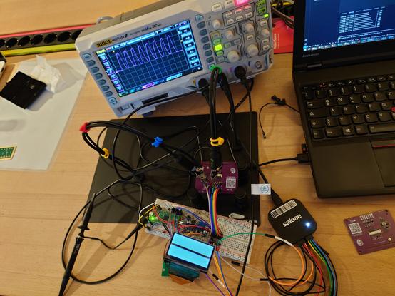
After a lengthy bring-up debug session, I noticed the #SSD1303 not quite behaving as I expected.
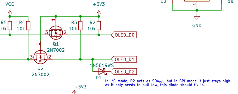
Pin D2 (SDA_out, which "should be left open" in #SPI mode) was not staying high all the time, like I had measured previously.
Rather it was shifting out some kind of gibberish data.
This was not compatible with my tested idea of "just putting a diode between SDA_out and SDA_in (D1)", to still allow I2C-lows through in #I2C mode, but block the constant* high signal in SPI mode.
* formerly believed as