Need better cable management? ➰ This TPU Cable Holder is flexible, grippy, and super easy to print! 🏷️ #3DPrinting #CableManagement #TPU #MakerWorld
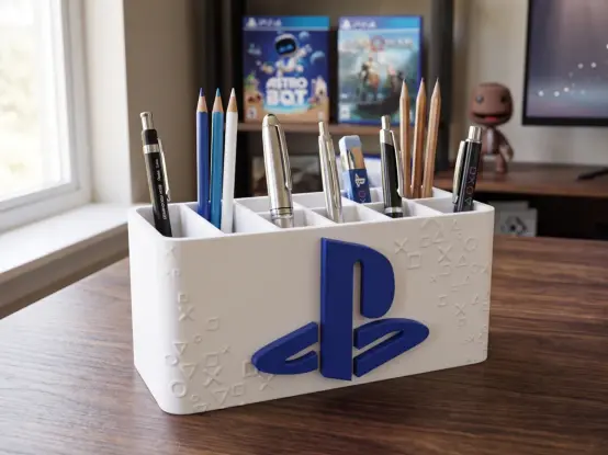
Level up your gaming setup! 🎮 This PlayStation Desk Organizer is perfect for keeping your gear organized and looking awesome. 🏷️ #3DPrinting #GamingSetup #DeskOrganizer #MakerWorld
https://makerworld.com/en/models/2816999-playstation-desk-organizer-pen-holder-no-ams
PlayStation Desk Organizer - Pen Holder, NO AMS - Free 3D Print Model - MakerWorld
Download this free 3D print file designed by vajcnerd. PlayStation Desk Organizer Pen Holder NO AMSTurn your desk into a gaming hub with this iconic PlayStation organizer.Inspired by the world of PlayStation, this stylish and functional desk organizer is designed for anyone who wants to keep their stationery organized with a gaming touch. It's the perfect addition to your gaming nook or desk.height 77mm, width 177mmthe logo is glued to the box
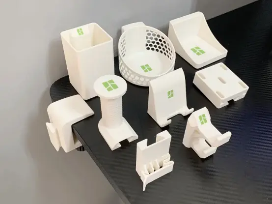
Level up your desk organization with this Modular Desk Organizer! 🛠️ Customize your setup to fit your needs perfectly. 🏷️ #3DPrinting #DeskOrganizer #MakerWorld #Organization
https://makerworld.com/en/models/1802763-modular-desk-organizer
Modular Desk Organizer - Free 3D Print Model - MakerWorld
Download this free 3D print file designed by Ms. 此模型是一个模块化桌边小工具,它拥有一个通用夹具,来实现多种不同的功能。它具有适用范围广、简约美观、坚固实用、无限拓展的特点。 特点:打印简单快速,简约实用。夹具40mm夹持范围,适配大多数家用桌面,打印坚固。榫卯卡扣,连接简单稳固。功能丰富(目前模块数量:8种),有其他需求或想法,可评论区留言。各部件均经过功能性验证,打印和使用非常不错,各部件(以及今后添加的部件,均在下方有详细描述)*模型均采用经过实际验证,功能性非常好的实用工具,发布时所有部件在一个文件中,您可以在集合中找到它,后续添加的部件均在名为“新增部件”中上传,以下为各部件的详细描述:*配件一直在持续更新,更多新增的配件正在开发中,建议您添加收藏,以免错过适合您的配件。 通用夹具:夹持范围0-40mm,进深33mm。采用易打印螺纹,4mm螺距,防滑条纹。螺栓中孔为默认强度下增强强度设计。模型自带支撑,打印后去除,无须支撑打印。夹持面微倾设计,加上防滑条,夹持紧固。榫卯卡扣,简单实用。连接稳固。耳机挂架:50mm内轴宽度,适配各类头戴式耳机。滚花设计,使支架具有防滑功能,提升质感。大接触面榫卯连接,承载力强。打印无需支撑。手机支架:适合经常在桌面放置手机使用。精心调校并多次优化的倾斜角度,手机放置特别稳定。预留充电空间,可在插上充电器的时候快捷取放。无需支撑打印。水杯支架:轻量化镂空设计,加强筋增加主体强度。内径80mm,适用于日常使用的水杯,或者饮料等。前端高度18mm,带手柄的水杯也适用。形状原因,少许轻微悬垂,不影响强度。skadis洞洞板:5mm厚度IKEA洞洞板设计。可多个拓展使用,组成无线拼接的桌边洞洞板。无需支撑打印。发布后已更新,下方加长,使下方挂钩具备全功能。数据线整理器:可同时整理3根数据线。采用弹簧卡扣设计,一体打印,无需支撑。带开启把手,使用简单高效。笔筒:采用50*50*80mm黄金比例笔筒设计。隐藏式榫卯部位,使两部件浑然一体,美观实用。壁厚1.9mm,间距强度与打印速度,无需支撑。挂钩:使用本人精心设计的两段式挂钩设计,坚固实用。已设置手动支撑部位,打印方向兼顾强度。托盘:每部62*67mm,小型托盘。可存放临时小物件,也可并排拓展桌面空间。 以下配件在名为“新增部件”打印配置中:skadis转接器:此配件为skadis洞洞板的转接器,可以将配件直接转接到洞洞板上面。通过转接的卡扣,有时候要比直接带skadis挂钩的打印更加结实,也大大减少了重新打印的时长和耗材的消耗。两种skadis转接器,以适配所有的模块化配件。大号储物盒:尺寸为100*75*80mm,可容纳更多的物品。采用包裹夹具设计,增大空间利用率以及夹持稳定性。此配件可搭配增高的skadis转接配件。桌边垃圾桶:尺寸为85*100*110mm,可当做现行垃圾桶或者大号储物盒。三面镂空设计,打印效果完美,轻量化设计。采用包裹夹具设计,增大空间利用率以及夹持稳定性。此配件可搭配增高的skadis转接配件。焊锡丝支架:直径60mm以内焊锡丝适用。周围镂空,每一个孔都能当做出丝扣。Gopro支架:适配Gopro的支架。手拧螺栓为M5规格,螺帽对边8mm,兼容Gopro通用配件。PS5手柄支架:适配游戏手柄的支架。尺寸可兼容PS4、PS5、PS5 Slim、Xbox等手柄使用。无支撑打印,此配件可搭配增高的skadis转接配件。手表支架:可放置手表,多个夹具可并排放置。毛巾挂架:这是一个毛巾挂架,但也可实现其他更多的功能。组装时对准L/R,旋转拧入螺纹,即可稳固固定。大杯架:这是一个加深大杯架,适合较大的水瓶使用。内径95mm,高度95-115mm。此工具为网友贡献图纸而来,感谢@LastDroftime01magsafe支架:适配magsafe,作为手机支架使用。角度53°,大大增大吸附的稳定性。适合放在显示器增高架等地方使用。 桌边拐杖支架:包含两种规格,任选一种合适的来打印即可。包含T型支架和C型支架两种。 Apple Watch充电支架:建议使用pla matte制作,较软的表面可极大地避免充电器划痕。带固定螺栓,防止卡槽脱落。方便整理杂乱的Apple Watch充电器。更长的夹具(50mm/70mm):在下载 STL/CAD 文件中您可以找到这两个的打印配置。文件为3mf文件,已设置好,下载后即可打印(需用电脑)。
Tame the cable jungle! 🌿 This Cable Organizer / Cable Clip is a must-have for any desk setup. Simple, effective, and easy to print! 🏷️ #3DPrinting #CableManagement #MakerWorld #Organization
https://makerworld.com/en/models/836148-cable-organizer-cable-clip
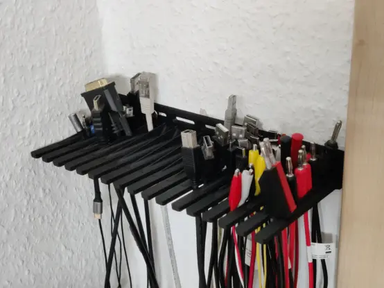
Keep your cables tidy and off the desk with this customizable Wall Mount Cable Hanger! 🔌✨ Perfect for managing power cords or headphones. 🏷️ #3DPrinting #CableManagement #MakerWorld #Organization
https://makerworld.com/en/models/1000351-wall-mount-cable-hanger-organizer
Wall Mount Cable Hanger / Organizer - Free 3D Print Model - MakerWorld
Download this free 3D print file designed by rngcntr. Inspired by the great model for CAT5 cables by stefaan.vandevelde.kortrijk, I designed this wall mounted cable hanger. It fits the most common cable diameters and the spaces are slim enough so that the most popular types of plugs will not slip through. Thick cables like HDMI just fit and small plugs like USB-C or headphone jacks are just wide enough to be held in place. The cable holder can be screwed to a wall or any vertical surface. Thanks to the variety of holes, it supports virtually any distance of screws. The model comes in two sizes, one with 16 and one with 13 slots for cables.
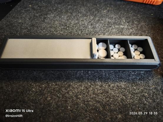
Pillenbox 2 war nach dem Urlaub beschädigt, also habe ich eine neue gedruckt.
https://makerworld.com/de/models/709370-sliding-pill-box#profileId-639661
Add a touch of Japanese aesthetics to your desk with this beautiful Asanoha pen holder. 🖊️ #Minimalism #MakerWorld
https://makerworld.com/en/models/1163443-asanoha-pen-holder-desk-organizer
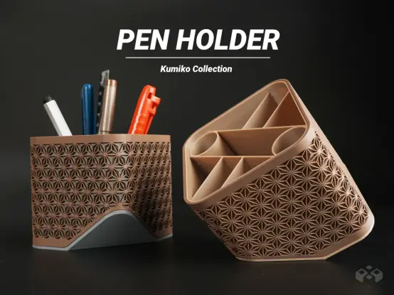
Asanoha Pen Holder - Desk Organizer - Free 3D Print Model - MakerWorld
Download this free 3D print file designed by Meyui. A Kumiko-style pen Holder designed for your workspace. It features 9 compartments for storage, efficiently organizing different stationery and tools.Dimensions: 95 x 95 x 90 mmThe slanted design makes grabbing tools more user-friendly. It offers spacious storage with a practical compartment design, making it perfect as a pen and tool organizer.Kumiko Design Style: Inspired by traditional Kumiko woodworking patterns with a modern minimalist touch.Functionality: Perfect for organizing pens, tools, and small office supplies on your desk. Slanted Opening Design – Easy access for improved usability and work efficiency.Boost MeThanks for your support!
Wahrscheinlich bin ich ja bloß ein alter Sack, aber nach 10 Tagen am Tablet und Smartphone bin ich froh wieder an meinem fetten Desktop-PC zu sitzen.
Und ich werde ihm wohl ein neues Gehäuse 3D-drucken.
https://makerworld.com/de/crowdfunding/251-modcase-hyper-premium-build-any-pc-one-case
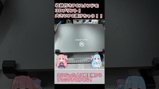
https://www.wacoca.com/games/1383296/ 【3Dプリンター】大きいゲーミングPCでも安定!収納付きPCスタンドを作ってみた #3Dプリンター #BambuLab #デスク周り #便利アイテム #ゲーミング #shorts ##GAMING #3Dprinting #3dプリンター #3Dプリント収納 #3Dプリント実用品 #BambuLab #DIY #Game #GameNews #games #GamingNews #MakerWorld #P1S #PCスタンド #PETG #shorts #VOICEROID #ケーブル整理 #ケーブル管理 #ゲーミング #ゲーミングPC #ゲーミングノート #ゲーミングノートPC #ゲーム #ゲーム攻略 #ゲーム最新情報 #デジぷらクラフト #デスク収納 #デスク周り #デスク整理 #デスク環境 #ノートPCスタンド #フィラメント #ボイスロイド #ラップトップスタンド #作業環境 #便利アイテム #便利グッズ #収納付きスタンド #実用品 #小物収納 #引き出し収納 #琴葉茜 #琴葉葵 #自作デスク
Einziger Pluspunkt: #MakerWorld ist so ein ekliger Walled Garden, der zwar alles Möglich als cc by hat, aber hinter ner Pay/Account-Wall.