@tedyapo Yeah, so Google Gemini. The code it gave me was almost right. I used it as an outline to understand how (extended) Kalman filters work and how to apply them to this problem, and steered me in pretty much the right direction. Best experience I've had with an LLM. It probably would have taken me longer without it, even though I did spend two whole days on it.

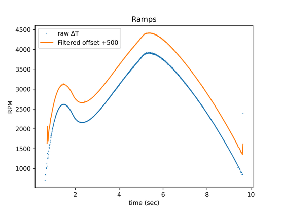
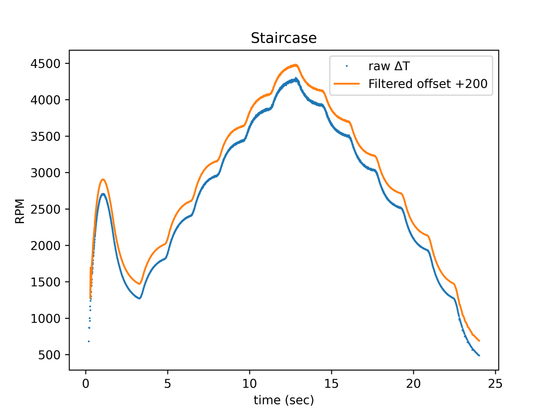
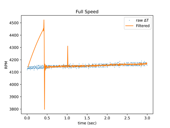
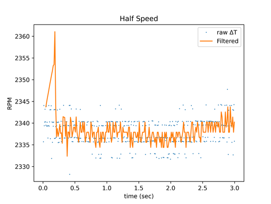
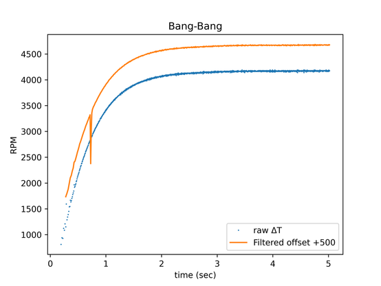
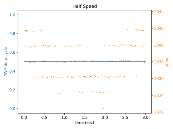
But there are glitches, and I don't know how to tune it to be smoother.

🧵 17/N

#FanSpeed #DSP #KalmanFilter

@poleguy @attie @rrmutt @tedyapo The Jupyter notebook is on Github here. It's not quality code, it's hacked together.

https://github.com/kbob/ESP32_Fan_Analysis/blob/main/analyze/kalman.ipynb

🧵 16/N

#KalmanFilter #DSP #FanSpeed #Jupyter

ESP32_Fan_Analysis/analyze/kalman.ipynb at main · kbob/ESP32_Fan_Analysis

Control a fan with PWM, read its tach, analyze and filter the tach output. - kbob/ESP32_Fan_Analysis

GitHub

@poleguy @attie @rrmutt @tedyapo I am not prepared to speculate on the glitches. I tried tweaking the knobs I know of to smooth the graphs, but it seems to be at a local optimum.

Graphs 4 and 5.

🧵 14/N

#KalmanFilter #DSP #FanSpeed

@poleguy @attie @rrmutt

@tedyapo nicely sent me a Google Gemini outline of a Kalman filter to measure fan speed. I used it as an excuse to learn about Kalman filters. I carefully transcribed it into Python, and now I've got a not-quite-working implementation. Here are the graphs, same data as upthread in 🧵4 and 🧵5.

Graphs 1-3 here, 4-5 in the next post.

🧵 14/N

#KalmanFilter #DSP #FanSpeed

@tedyapo @poleguy @attie @rrmutt Absent any good ideas from the peanut gallery, I think I'll try an IIR filter next. I think I can work out the math for a variable-sample-rate IIR.

🧵 13/N

#FanSpeed #DSP #IIR

@tedyapo @poleguy @attie @rrmutt (This project is on my travel laptop, so I'm only working on it sporadically. D'oh.)

I did the CIC thing. I created samples where pulse present = 1 and absent = 0. Integrated, decimated, combed. The problem is that that's a DC signal. Integrators overflow on DC. I want to measure the DC bias (pulse density), so I can't just decay the integrators.

Suggestions welcome. (cont'd)

🧵 12/N

#FanSpeed #DSP #CascadingIntegratorComb

I pushed my firmware and my analysis notebook to Github.

The repository is here.
https://github.com/kbob/ESP32_Fan_Analysis

The Jupyter notebook that created the upthread graphs is here.
https://github.com/kbob/ESP32_Fan_Analysis/blob/bb9b301058848362991cbcb2453ec73eb7901afd/src/fan%20analysis.ipynb

#FanSpeed #Jupyter #YourBiggestFan

GitHub - kbob/ESP32_Fan_Analysis: Control a fan with PWM, read its tach, analyze and filter the tach output.

Control a fan with PWM, read its tach, analyze and filter the tach output. - kbob/ESP32_Fan_Analysis

GitHub

Let's find those bands and see what's up. I analyzed both the half speed and full speed runs, as they both show the banding clearly.

The space between bands is 813-824 clocks, or 97-98 KHz. I can only guess why they're different.

If I understand Nyquist correctly, I can down sample my traces to 200 KHz and not lose any resolution.

#FanSpeed #Jupyter #YourBiggestFan

My next hypothesis is that the tach signal is not a direct measurement of some analog signal but is generated by the fan controller and is quantized by the controller's clock.

So let's switch from looking at RPM to looking at intervals. This graph shows the same data, but the Y axis is the interval between edges, measured in ESP32 APB clocks (80 MHz). There are two pulses per fan revolution, so I've colored the two pulses differently.

#FanSpeed #Jupyter #YourBiggestFan

I re-plotted the half speed run, calculating speed using the intervals between rising edges and the intervals between falling edges. These plots show both, all in one color. (Maybe I should have colorized them again.)

The small bands gaps are gone. There are still bands, but they're evenly spaced.

#FanSpeed #Jupyter #YourBiggestFan