One of the most annoying things in #electronics: you can run a trace under a 0603 resistor, but you can't do that under a 0603 capacitor. The IPC footprints are slightly different, taking the height of the capacitor body into account.
@niconiconi depending on the size of the trace, yeah?
@amsomniac Yes, but it's never a good idea to push the design rules too hard just for running a trace.
@niconiconi stupid question: what are IPA footprints? 👀
@exus1pl Typo. I meant IPC.
@niconiconi uff, I was afraid there was something important library or standard that I missed 😃
@niconiconi simply have smaller traces :V
@panegyr Are you going to pay the extra manufacturing cost for everyone who's going to use this PCB design in the future? If so, OK.

@niconiconi this is one of the reasons I don't include footprints with my auto-generated Altium & KiCad libraries for JLC's parts.

however, I *am* working on a thing that lets you turn their EasyEDA footprints into Altium/KiCad footprints, to get around this annoyance.

@niconiconi although the thing will probably have to just be a tool to locally convert them because I don't think there's a way I can distribute the footprints without incurring their wrath.
@gsuberland "to get around this annoyance." But it's incorrect to get around this annoyance, IPC says no because capacitors are not resistors with a different aspect ratio, mixed footprints degrade yield during reflow, perhaps by creating more tombstones. I also don't understand what does JLC have anything to do with it. This is the industry standard.

@niconiconi no no, I don't mean the standard is annoying!

I have a tool that generates parameterised parts for Altium and KiCad from the JLC parts DB. people often asked why I don't include a footprints library to go with it, and this is one of the reasons - I don't have the height data to generate correct IPC footprints for the parts, so I don't. it's an annoyance in the sense that it'd be nice if I could include footprints.

@gsuberland Interesting. But how useful would that be? What are examples of parts that are both useful and parameterizable? Most ICs follow JEDEC and use IPC footprints, so no need to auto-gen those. Most connectors have strange vendor-specific footprints, and you can't auto-gen those, and most two-terminal devices are also in standard packages. The only non-standard 2-terminal parts that I remember that I used are gas tubes and transient suppressors, with footprints taken from the datasheets, none of which is particularly autogen-able.

@niconiconi the parameters are stuff like resistance, power rating, voltage rating, etc. so you can search them easily in your libraries.

the footprint is a convenience thing. drag drop a part into your schematic, and the footprint is already assigned.

the way I do it right now is I just give each component entry a generic footprint name ref, so as long as you have a footprint called "R0402" or whatever it'll use that. but you're responsible for making that to your needs.

@niconiconi but I explain it a bunch in the readme. there's stuff like density class to consider, for example. makes it a big pain if you wanted to have a convenient drag-drop solution for all passives (which is generally why people seek my libraries!) - there are quite a few variables on 2-pin passive footprints even with just the IPC standards.

@gsuberland @niconiconi there’s also the cases where JLC’s footprints are hilariously wrong (yes, it was a TI power-related part with horrific CAD drawings)

EDIT: TPS55288, https://aus.social/@jpm/114180387563569695

I love this, so I (@[email protected])

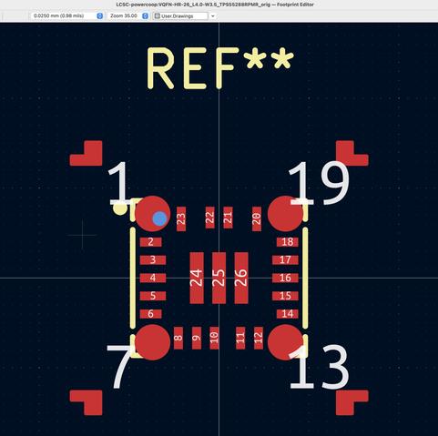
Attached: 1 image It is, however, marginally more correct than JLCPCB's attempt at a footprint for the same part.

Aus.Social

@niconiconi Works with a 0.25mm trace, but 10mil won't fit.

Revenge of the metric system :)

Slightly related: I was involved in re-generating the RLC footprints a few years ago. We did try to follow IPC as close as possible.

@cccpresser PCBs are still sold by mils, with a 10 mil/10 mil board being the de-facto cheap class. This is one of the other headaches in electronics: metric feature sizes are always slightly smaller than the imperial feature sizes. If the board design is metric, you're forced to move one step up in the pricing hierarchy, because your metric features exceed the imperial minimal by a few micrometers! In this case, the 0.25 mm trace is under the 10 mil minimum by being 4 micrometers too short!
@niconiconi What are the manufacturing tolerances? Would shrinking the cap pad sizes by 2 microns really make a difference?
@niconiconi @cccpresser had no idea about the diff between mils and metric. I figured if you kept to the manufacturers stated feature size, everything would be ok.
@niconiconi
> taking the height of the capacitor body into account
afaik jlcpcb screw around with paste apertures to their taste. If it's just about the solder volume / resulting fillet shape there'd be other ways to get good results unless it fails because production files are altered.
@niconiconi Where are you going where there's a difference in price for 10/10 vs. 8/8 (or .25/.25)?