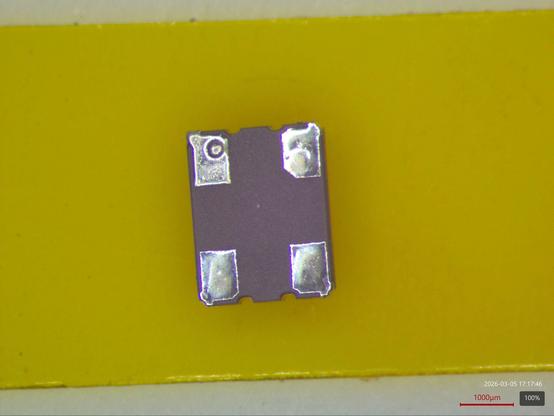
OK, oscillator failure analysis step one: Cleaning residual solder off the underside so it sits flat on the mill table. Then a final cleaning with acetone to get any flux residue off.

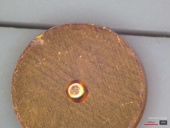
I wasn't sure if I could mount it to the mill table without it flying off because it was so small, so I mounted it to a ~1cm copper disk with some crystalbond wax.
This will make it much easier to find if I drop it, and give more area for me to attach to the chuck with double-sided tape.
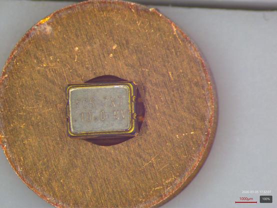
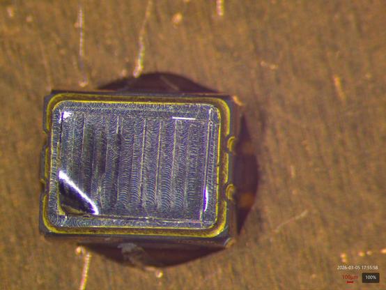
Pretty happy with the results for a surgical decap.
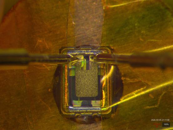
It looks like the quartz crystal sits on top and the oscillator driver is under it. Unfortunately we can't see the oscillator die without destroying the crystal.
Nothing looks obviously damaged, I'll do some higher mag images next.
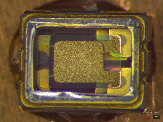
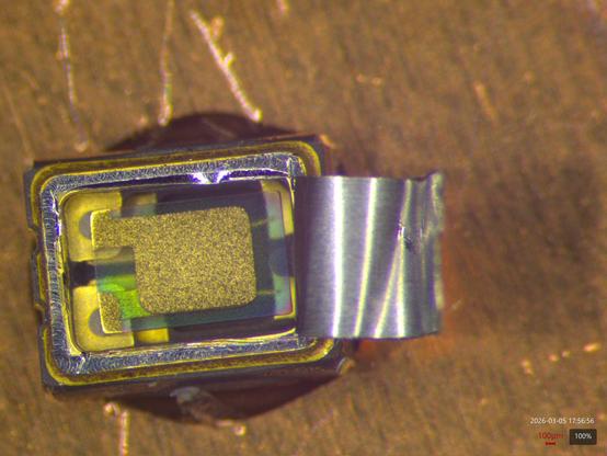
Composite of three focal planes (upper bond pads/crystal surface, lower bond pads, top of package) on the Labsmore/Mitutoyo system.
The left two pads clearly have connections to the driver IC but aren't very visible with the DOF of this system at the chosen focal planes.
It's interesting that the quartz is a somewhat textured surface, I expected a mirror polish.

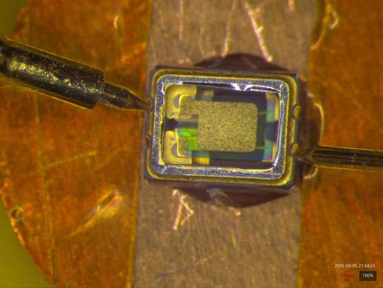
Nothing looks obviously broken here. Given the fact that the thing isn't oscillating and the history of ultrasonic cleaning I expected to see the quartz plate come out in multiple fragments (one of the reason I wanted to be so cautious opening it, I didn't want to lose shards of it).
Any ideas on other tests or angles I should do before I try to remove the quartz (likely destroying it in the process) to expose the controller die and see if maybe something is up with the wire bonds?
I don't think I can test electrical connectivity between the quartz and the mounting pads with my current setup, gut feeling is that touching it with any of my existing probe needles would shatter it. Maybe I'll try if I'm going to rip it out or something.
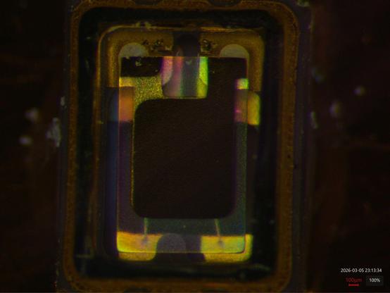
Wire bonds from the controller die to the package, seen through the quartz crystal so pretty blurry.
But they definitely look like second / wedge bonds from gold ball bonding.


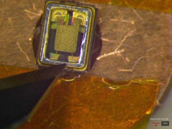
Bottom right terminal with focal plane swept from top surface down to the package pad.
No visually evident damage or cracks here.


S21 of the resonator measured at the gold pads on the substrate as best I could. The noise in the left area is me moving the probe into position, I couldn't position the probes and trigger the sweep with only two hands.
Interestingly it seems to resonate at 20 MHz not 10, I guess there's a divide by 2 somewhere in the output stage?

Oh yay, I thought my wife had gone to bed already but she was still up. Got her to click a few buttons for me and now I have a photo of the measurement setup and a clean VNA sweep with a wider bandwidth.
Sure looks like the resonator is intact.

Anyway, that's multiple pieces of evidence to suggest something catastrophic happened to the controller chip and that the resonator itself is fine.
So I guess I'm at the point where I need to rip off the quartz crystal to see what the controller looks like.
I just realized I'm an idiot. Looking back at the original photo I don't think those side castellations I was probing actually connect to the internal pins at all.
Meaning my open circuit measurements aren't valid. Too late.
Anyway the quartz element came out without significant visible damage (so I could hypothetically re epoxy it back in although I'm sure it would have parametric shifts lol)
Here's the controller bondout

@azonenberg Thanks for the thread. Thinning and cutting with a scalpel seems to work much better than I expected.
I expect you will, but it'd be cool to have a few higher resolution pictures of the die.