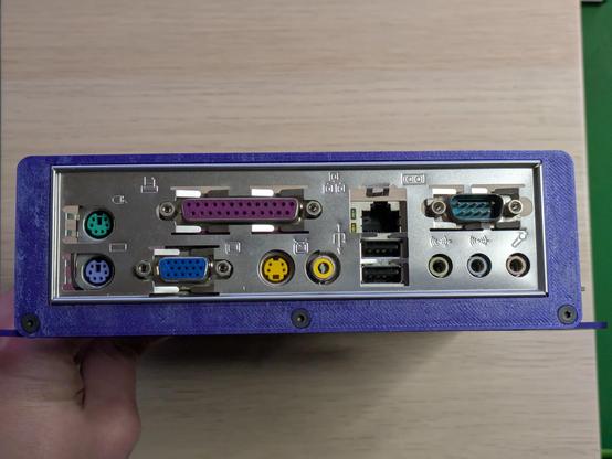
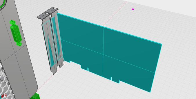
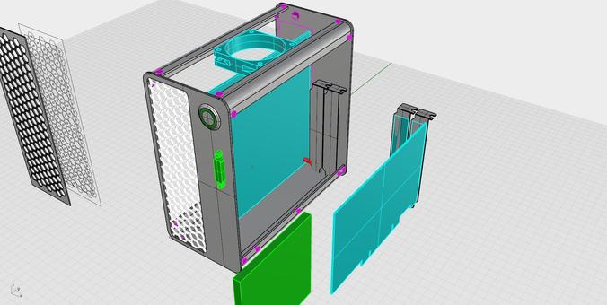
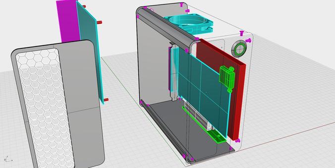
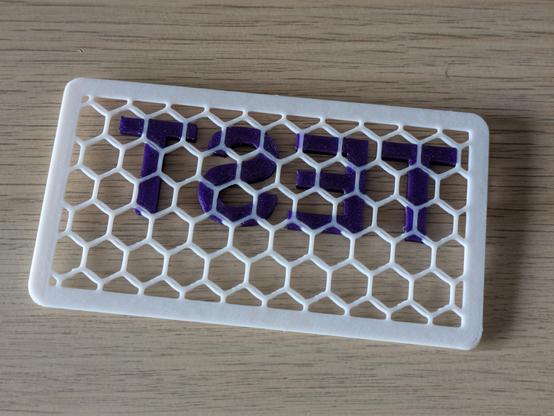
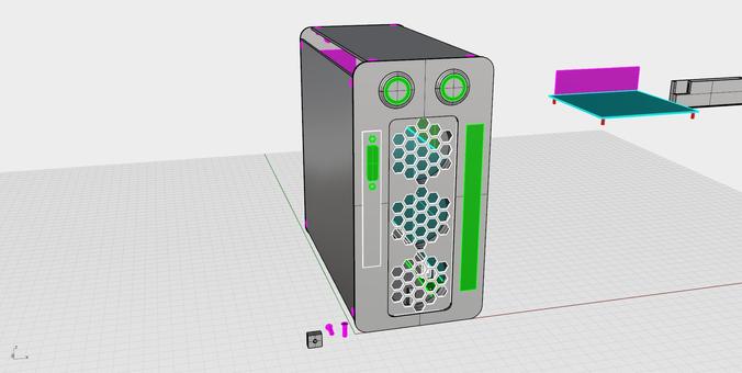
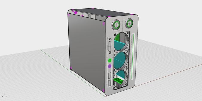
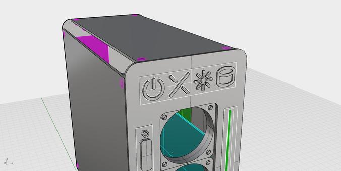
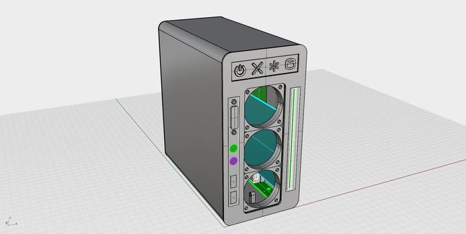
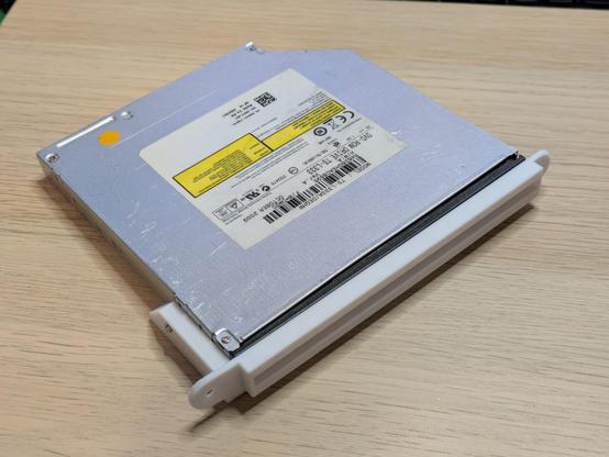
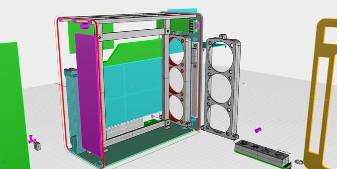
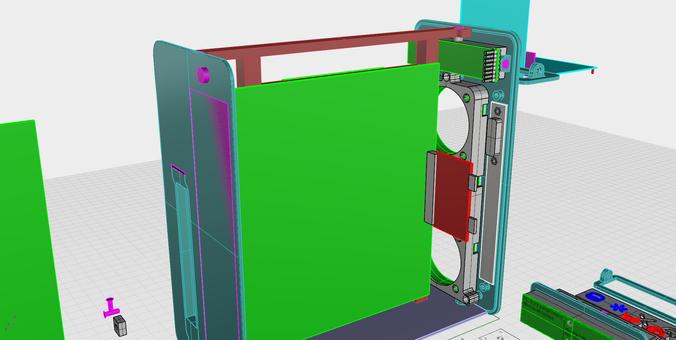
Some old renders of a SGI-inspired project from a few years back. I had a 3D printer at this point, but not one with a bed big enough to make 20x20cm panels, so the structure was built using laser-cut acrylic with 3D printed brackets bolted onto it.

I did actually get a mostly functioning PC case out of this idea for a while, and there are Many Learnings from that project that have rolled forward into present ones. Unfinished projects are never waste if you learn from them!

A much later render of the concept on the right, here. The top half of the case held the PC itself, the video card and power supply took up the bottom half, so the front grille got divided into two parts. A 180cm fan sat behind this, and actually blew out forwards through the *front* of the case - the grille was painted with thermochromic material so it changed from black to white in places as hot air was exhausted.

I'll try and find photos of the finished case and that colour changing effect.

Philosophical question for tonight. If you were an old ITX motherboard, where would you hide?
Follow-up philosophical question: if you were an old ITX motherboard's *backplate*, where would you hide?

The relationship between where a motherboard and its backplate sit in space is a complicated one, but I appear to have nailed it in the two really important dimensions. I'll print another of these tomorrow that slides the board about 2mm closer to the back of the case.

If the rest of this goes as smoothly as this part has, I might aim to make two of these cases - one for a 98-era PC, and one for an XP-era one. It'll be a challenge fitting two different sets of requirements into the same design.

Having wrangled the issue of motherboard placement, today I'm looking at the second-most annoying part of PC cases: expansion slots.

I find these particularly irritating to design for - do you hide the back of the card half an inch into the back of the case? Do you make the top of the bracket protrude? Do you take the bracket off and make something bespoke to screw directly to the card? I have a few things to try out.

There's also the question of whether I try to jam two slots in there, or just the one.

I don't think I need two - the Win98 box will have a Soundblaster there, the XP machine will most likely have a single-slot 8600GT. And fitting a second anything in there will make it tough to include a CD drive or even a 2.5" hard drive in there. So I think I'm planning single-slot for now.

Here's why PC cases that look great and proportional and sensible on the front look like a jumble of rectangles on the back - you end up with stuff clustered together, next to wide open spaces you can't make use of. I have a hard target of putting a CD drive in on the front, spaced very neatly and proportionately against the power button and the gameport socket, but doing so means putting the soundcard and its PCI extension board very delicately in the middle of everything.

Well, that appears to be the required geometry for holding a PCI card. This part will get printed directly to the back wall panel of the case, no need to make it removable.

This model of PCI SoundBlaster includes a bank of pins for plugging in a gameport socket - when new, that would have come on a separate bracket to be screwed in next to the card, but most cards like this are sold without that. They're not impossible to reproduce, though - I'll make my own to attach to the front of this case.

And when I say "not impossible", I mean "I've made them before". If you happen to own a #SoundBlaster card with the 15-pin gameport joystick header but nothing to plug into it, reach out!

Edit: Note that not all cards came with the headers physically installed, so if you've just read this and are about to go browse eBay for SoundBlasters, pay close attention to the photos to see if the pins are even there - I don't know if soldering pins in makes the gameport work or not.

Tonight's philosophical question: If you were a very small bag of M2 size screws, where would you hide?

I've managed to use 3mm metric hardware everywhere so far in this project, but slim CD drives mount using 2mm screws. I own....... some, somewhere.

Close enough for tonight - this is a 3D printed mount for a slim CD/DVD drive. These things are a weird shape and take the smallest screws of any standard computer hardware, and it took three goes to get this good a fit.

The white residue on the face is just glue from the print bed - each part that makes up the final case will be cleaned first.

That's the last of the complex parts - most of the rest is stuff like mounting buttons, a cooling fan, and aesthetic tweaks.

Ugh, it's hard to buy a decent 80x80x15mm fan. I miss the days where there'd be 50 different brands of fans in every size overflowing in every computer shop. Now it's all $40 Noctuas and one out-of-stock Silverstone or Deepcool. The industry standardising on 120/140mm fans is great if you're building a PC in a standard gigantic size, but nothing much smaller.

Maybe someone'll rock up to the vintage computer thing tomorrow with a box of fans I can rifle through.

What are the chances that purchasing this actually results in receiving an honest-to-goodness Arctic Cooling product? https://vi.aliexpress.com/item/1005008470980722.html

There's plenty of biggish-brand stuff on Ali these days, is it just counterfeit nonsense or maybe the genuine product sold out the back of the factory? I doubt "Shop1104078524 Store" in China are an official Arctic reseller.

Five iterations in and I think the slim CD mount is final. The screw holes line up, the fit is snug but not too tight, and I have a pretty high degree of confidence it'll work.

See the scratches on the top of this drive? It's dated October 2009, but I bought it just a couple of years ago on eBay as a "new" cheap USB CD drive. You get what you pay for with cheap electronics, and apparently the cheapest price gets you a refurb drive from a junked laptop.

This next one might be more interesting than the same CD drive again. My printer can automatically swap filaments mid layer, so I wanted to try making a 3D printed fan grille with an embedded logo/text. Those letters weren't made separately and glued on - they're printed in place!

I have some tweaks to do to make the grille itself look neat and even, and purple on white was not a great colourway in the end, but I'm calling this a successful concept test. #3DPrinting @3dprinting@a.gup.pe @3dprinting

Here's where I'm leaving the project tonight. I fell in love with an asymmetrical front panel, but the reality is this is easier to balance and I think I have a source for okay 5cm fans that will work with this. It also frees up all four corners for mount points for all the side panels.

Downside is that it now looks like a horrified screaming robot, but that has its own charm and appeal too. Maybe there's still something wacky and asymmetrical I can do with power buttons and lights - any ideas?

15-pin gameport, PS/2 keyboard and mouse, and two sockets for that new-fangled USB standard that probably won't catch on. What more front I/O could you possibly want on a Windows 98 machine?

I've just made a fair bit more work for myself in fully kitting out this front panel, but I think all the "big" case problems are now solved.

The four horsemen of vintage PC enthusiasm: power button, reset button, power light, hard drive activity light.

The power and reset button parts extend through the faceplate to press buttons on a circuit board underneath. The two light glyphs will sit atop a super-thin 3D printed layer with a bright LED underneath, so the whole right side of the panel will glow.

The design and scale of the individual bits will change before the final version, but I'm pretty firmly wedded to this idea overall.

How's it possible that I can just *make* my own buttons? Well, these exist - these are momentary tactile switches with a square nub on top, meant to have these colourful tops click on to them. I can make a simple circuit board with two of these, and two LEDs, 3D print some bits with my power and reset symbols to pop on, and then it's just two wires from each LED and button to the motherboard. That's functionally all that you're pressing on your own PC case to turn your computer on.

As for the LEDs, I'm hoping these will do the job. These are 15mm square diffused LED panels - they were Adafruit product ADA4040, but it doesn't look like they sell them anymore.

I can easily test what these will look like through a thin 3D print. If they're not bright enough, I can pivot to using super bright LEDs.

I won't need to worry about a current-limiting resistor in this assembly as PC motherboards do that anyway for their indicator LEDs.

Okay, that's working beautifully so far. The photo is exaggerating the brightness, but not by much! That's shining through two layers of 3D print - I might even increase that to dull it a little.

The intricate button holes on the left would require support material underneath to print this whole structure in one go, and my AMS is a little broken at the moment, so I can't actually do more than two different filaments in one print right now.

Okay, here's where the front panel sits after day seven. I have a pretty solid proof-of-concept for both the buttons and LEDs for the front buttons and lights - can anyone suggest a different reset button icon that isn't just a circle with arrows on it? Ideally it needs some mass in the middle.

Next step is the internal structure - I think the top and sides will be one U-shaped piece, but that means the front, back and base plate need to stand on their own, with a frame for the motherboard.

My plan to work on the internal structure has led me straight back to the CD drive again - I have a plan to attach the front, back and bottom panels together, but I want to get the front stuff fitting before I can print a full front panel. This kerjigger will screw into the front panel from the inside.

Modelling off this beat-up, second-hand, slightly bent in places drive probably delayed the project a couple of days due to wasting a few iterations on its own eccentricities.

This is the 3D modelling equivalent of a cluttered, untidy desk, but I have at least a V1 print-worthy design for the CD drive mount and the bracket for the fans. That will need some cutouts for the fan wiring to escape, but I'll wait for the fans to arrive so I know exactly what I'm dealing with before I do that.

I think I've entered a new phase with my #PCB design skills. Being able to sketch the layout in #Rhino3D where I'm relatively skilled, then export as SVG and then just line up the handful of actual components just so in Fritzing has been great.

Today I've discovered the existence of "single line" or "single stroke" fonts - apparently used in engraving, but also useful for text on PCBs. The one I'm using here is "MecSoft" from the Rhino people themselves: https://wiki.mcneel.com/rhino/engravingfonts

This is more or less how the top of the front panel will look when complete. These just look like static icons, but the power and X things are tactile push-buttons, and the star and disk will hide bright blue LEDs for status lights. (Ignore the little orange breakout board, that's just holding the buttons in place.)

This is 10cm wide, which is the full width of the final case.

The sparkly black filament hides many crimes, but not under-extrusion - I'll have to tweak that for the final panels.

Ok, decision time. What looks better: the 'split X' or the circle-with-arrow for a reset button? The circle's the better symbol but looks very similar to the power button. The X looks more balanced on the panel overall.

Both are perfectly functional as physical buttons, the total width and height of each glyph here is only 12mm so even an empty-ish circle works when firmly pointed at with a fingertip.

The circle version needs a bigger arrowhead, otherwise I'm happy with its appearance.

The people have spoken, almost nobody liked the 'X' reset button... but I really don't like the circle one either, so here's a first draft of a squared-off one that will look a bit more balanced amongst the other three. Getting it to look right by itself will take a few goes, but the PCB to mount all this to won't arrive until next week sometime.

Here's the little setup I'm using to test these. The Pro Micro is just there to provide easy access to 5 volts and ground for the LEDs, the buttons don't do anything but make a satisfying click.

The camera likes to wash out the light under the indicators - in real life the effect is a much more even blue. The LEDs are these: https://www.adafruit.com/product/4040

A 0.1" pitch breadboard isn't quite the right spacing for this, but the tolerances are high enough for things to fit together right.

Some actual computer parts arrived - a CompactFlash to SATA adapter, a SATA-to-also-SATA-but-the-slim-optical-drive-version adapter, and then a dual parallel-to-serial adapter to connect both drives to the PC itself.

Using SATA drives simplifies the data cabling, but power cabling is still going to be a mess of adapters - the PicoPSU I have gives me one SATA and one 4-pin molex power plugs, but I need two SATA for the disk drives and one 4-pin "floppy" for the PATA adapter.

...and here's the next technical problem to solve: that dual SATA to PATA adapter is exactly as tall as the space it has between the motherboard and the side of the case. This is a very small component in the hand, but it becomes enormous when modeled in 3D with the rest of a compact computer.

I don't want to design my own right angle riser PCB thing for this, so I'll find a very short 40-pin cable extension and run it behind the motherboard or something.

Okay, I'm pretty much in love with this iteration of the front panel buttons and lights - this version of the reset button feels unexpectedly modern somehow.

The reset icon needs to be moved upward slightly for balance, I need to iron the top surface for neatness, and some other dimensional tweaks etc etc to make it physically mount well, but that's the hard work done.

Speaking of the top surface - I might print and glue on a 1- or 2-layer fascia for the front of the case for final prettiness.

Well, that's an interesting result. Ironing a 3D print usually produces a more matte finish because the surface is so much flatter, so with sparkly PLA it produces a surface that looks like it's been very neatly carved from a glittery rock. I'll definitely be printing and attaching a separate faceplate to the PC case for finishing looks.
(And just to be clear, I don't mean with an actual clothes iron - there's a setting in modern 3D printing slicers called "ironing" that does one last, very fine, very low volume pass over a finished surface to smooth it out.)

It's starting to look like something.

There are flaws - some stuff didn't line up right, some lined up too well (there's one screw trying to poke through the front panel), I've stripped one plastic screw socket, and I appear to have forgotten to allow room for a fan grille of any kind. But these flaws are also lessons, and things I can fix, and I'm becoming quite excited by this little project!

In fact, looking at this now - I could probably print the front panel and all of these bits in one monolithic piece for strength. I've designed each individual part separately so I wasn't reprinting one large part over and over with tiny changes, but they don't have to stay modular.

One single part, printed with breakaway supports, and surfaces I can glue prettier faceplates with better finishing to, which then gets bolted to the rest of the case structure - I think that's the way forward now.

Phenomenal cooling power, itty bitty mounting space. These are 50x50x10mm fans, and I'm cramming three of 'em into the front of this little case. The little 1GHz VIA C3 CPU that will live in here definitely doesn't need this much airflow, but the XP machine that will inhabit v2 of this case might.
@timixretroplays ooh, XP as in Pentium 4, as in the toaster chip they had to introduce thermal throttling for?
@jpm it's either an E6600 or Q6600 (2.4GHz Core2 Duo or Quad respectively), can't remember which one I bought, and probably a fanless 8600GT. That's pretty much exactly the setup I had in a Shuttle XPC cube like 20 years ago: https://au.shuttle.com/products/productsDetail?pn=SD32G2&c=xpc-cube
Shuttle Australia || SD32G2 - Products

Shuttle, a leading PC manufacturer specializing in high-performance desktop PCs in compact designs offers a full range of products, from XPC, AIO to Slim PC.

@timixretroplays avoiding the NetBurst heaters and going back to the original Pentium Pro, Pentium 2, Pentium 3, and Pentium M bloodline.