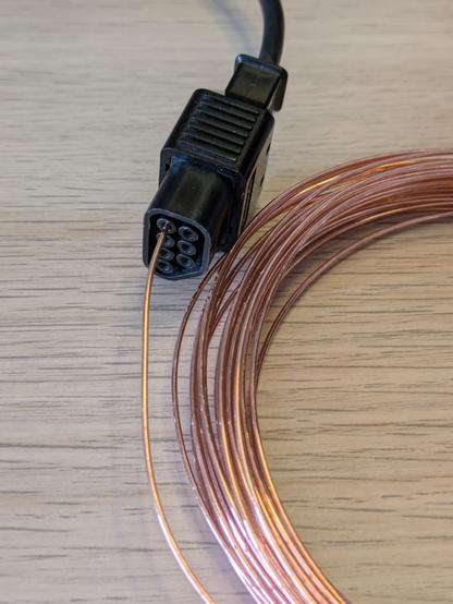
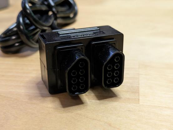
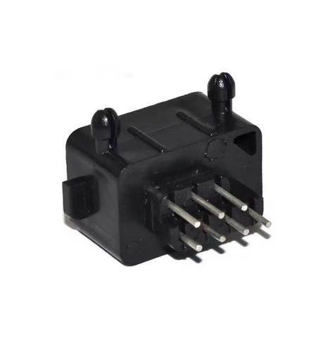
The eternal battle of needing an adapter for an old game controller I've collected - but retail ones are only available from the US for $toomuch, and hobby-grade versions for half that on eBay... then buying a handful of the connectors on AliExpress and resolving to make my own instead.

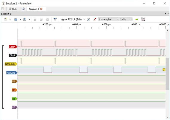
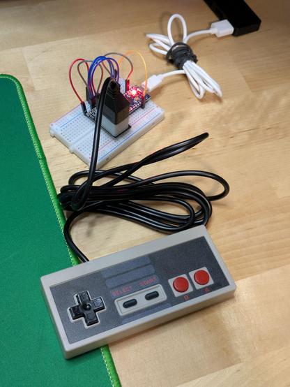
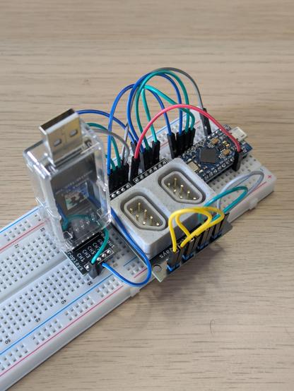
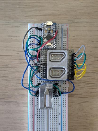
I mean, the NES controller looks trivial to read from, you just blip one pin and read from another: https://www.allaboutcircuits.com/projects/nes-controller-interface-with-an-arduino-uno/

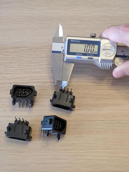
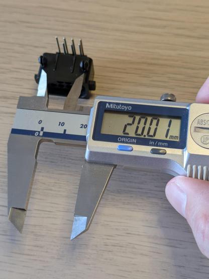
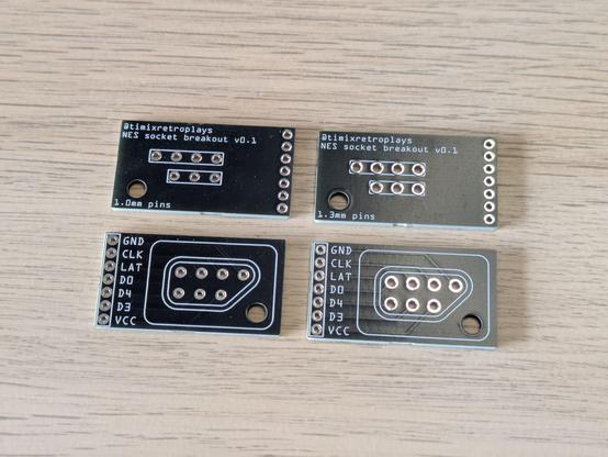
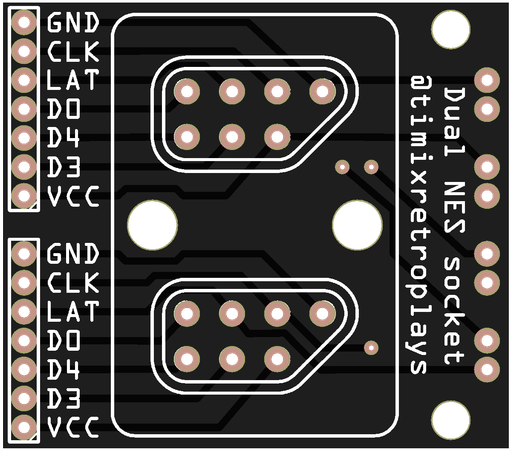
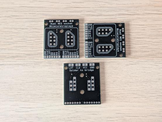
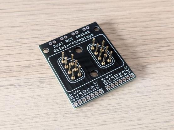
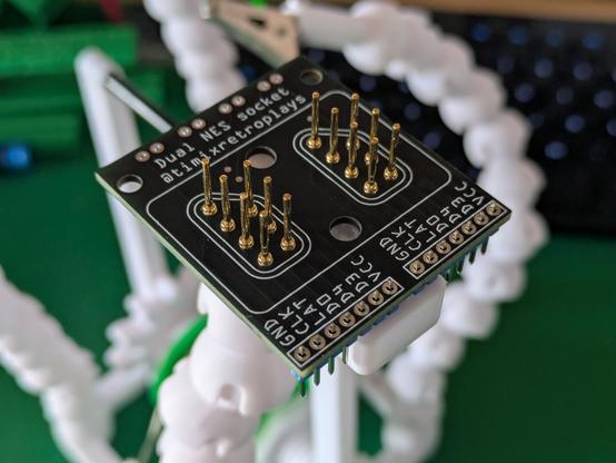
The hard part is making a PCB to match. Sounds like another #SimpleBreakouts project!

Part of what makes these slightly hard to find, I think, is the rarity of the sockets. The NES is now over forty years old and I doubt anyone's caused a factory to produce more parts for them since at least the year 2000, so anyone making commercial adapters will be doing so in very small quantities.

Mayflash, for example, seem to have given up on that approach entirely, and their adapter uses a 9-pin connector and (I suspect) a butchered extension cable to make it work: https://www.mayflash.com/product/PC053.html

PC053

Connect your SNES/SFC or NES/FC controller to your PC Windows or PS3

A thing I'm noticing though is that the older and simpler a piece of technology is, the easier it is to replicate at home with currently tech. It's trivial to make an Arduino behave like an XInput device, for example, which means you could build a completely custom XBox controller if you liked. We can clone complex shapes like modern gamepads by 3D scanning and printing. And the NES gamepad socket might be simple enough that you can replicate it today with a 3D printer and some bent wire.

So, the goal for this mini project will be an Arduino 32U4-based adapter with a couple of 3D printed NES controller sockets on it. That could be replicated for well under AU$10 by someone with the right machinery and skills if someone (I'm the someone!) wants to burn some spare time in making a design that will work, and most of that cost is in the Arduino-compatible board - the rest is cents of plastic.

Worst case, I'll build a few with the official sockets, and make those available too.

It'll be weeks before I have any electronic parts to play with, but for now I have a 3D printed socket that perfectly fits the plug on one of my NES controllers. A 0.4mm nozzle isn't fine enough to print walls between the pin shrouds in the connector, so my version will look open like this.

Do you have a 3D printer, a NES controller and half an hour to kill? DM me, I'd love to test this part on other printers and with other random controllers people have in the cupboard.

#3DPrinting

Today's research reveals there are differences with the controllers between PAL and NTSC NESes - some PAL systems require PAL controllers with specific pull-up resistors in them, but NTSC systems can use either. My adapter will be "NTSC-like" and not include the extra diodes in a PAL-E system, so it should work with all controllers, but it does mean, thanks to the existence of PAL-E Four Scores, it's not possible to make a universally compatible adapter for every possible controller combination.
Another tidbit is that two of the pins in the NES 7-pin connector are unused in standard controllers, but are extra data pins for things like a light gun; to my understanding those only work on a CRT, and I have no idea what you'd need to do to get that working through an emulator, but I'll connect those lines in my adapter and leave them usable in case someone wants to hack some kind of accessory support in there.

I think, with a 32U4 Pro Micro clone, I can support up to four controllers with all pins wired up. That's clock, latch and 3x data lines per controller, which is 20 in total, but I think I can make the latch pin common to all ports - that's the one that causes controllers to reload their states into their shift registers for reading.

I think the MVP for my adapter will be two ports - both the Advantage joystick and Four Score adapters have two plugs - but a four port variant should be possible.

Reading from a NES Four Score looks trivial.

For a regular controller, which is basically an 8-bit shift register, after strobing the latch pin, strobing the clock pin 8x will reveal its D-pad and button states, and you do the same again on the second port for the second controller.

The Four Score appears like a 16-bit register, so you flick the clock eight times to read player 1's pad, then another 8x to read 3. Then you do the same to port 2 to get players 2 and 4. https://www.nesdev.org/wiki/Four_player_adapters

Four player adapters

Four player adapters are devices that plug into controller or expansion ports and provide additional ports. These ports can be used as alternatives to hardwired controllers or for multiplayer with more than 2 simultaneous players. Contemporary adapters allow some consoles to interface with up to 8 controllers...

NESdev Wiki

The Hori 4 Players adapter (15-pin "Famicom Expansion" plug) looks identical to the Four Score in terms of protocol, and while nobody appears to have documented exactly what the NES Satellite does, I'd be very surprised if it did anything differently at all.

Satellites are also not particularly difficult or expensive to get, either. I foresee a new mini collection brewing... but I'll force myself to wait and validate my NES MAX pad working with my adapter before I start acquiring more hardware.

Raphnet's 4nes4snes board combines the clock and latch signals for all four controller ports, so that's proof that's doable - four controllers readable with just six pins, or 14 if I want to hook up the extra data ports too (which I do). A Pro Micro has 18 digital I/O pins available, https://www.raphnet-tech.com/products/4nes4snes/4nes4snes_controllers.png

Here's my vision for the NES socket: a #3DPrinting frame for wires bent at a 90 degree angle to be pushed into, with one end pointing out into the socket for a plug to slide onto, the other out of the frame to go through holes in a PCB to be soldered down.

I will also make some sort of jig for precisely bending... some sort of wire. I know not to use anything galvanised as the fumes from soldering it is toxic, so my first attempt will be with 1mm copper jewellery wire - any other suggestions?

That settles it - the pins in a #NES controller socket are of 1mm thickness. This validates my measurement from the photo I saw.

This is with the current reproduction socket, of course; there is still the guy who measured his at 1.2mm (method unknown), and the other guy who made his own controller using sockets that took 1.3mm pins. It's possible the original hardware used thicker pins, but the 1mm jeweller's wire I bought on a whim seems to make a solid connection in this OG controller plug.

The pins in the socket itself are on a 4x4mm pitch, the two rows of pins that go to a circuit board seem to be intended to be 3mm apart.

The spring clips seem to need a 4mm hole. The centre line between the two clips seems to be 10mm from the centre of the nearest row of pins, and the clips themselves seem to be 20mm centre to centre.

Reverse-engineering stuff made to metric measurements is so much more pleasing than those made in old money. Japanese hardware just hits different.

#Fritzing has never felt *completely* comfortable to me - it somehow feels both overcomplicated and underpowered for making simple boards like this - but it remains the only PCB design tool I've ever been able to open and just make a thing in without poring over documentation about vias and footprints. You drag and drop stuff, you fettle with the exact positions of things by slightly changing numbers, and you can export everything to a file PCB makers understand - and that works for me.

It didn't escape me that 1mm pins are thicker than what I'm used to - if you buy typical 0.1" header pins, you'll get ~0.6mm square pins that perfectly fit the apparently-default 1mm through-holes.

I'm *fairly* confident 1mm round pins will fit into 1.1mm PCB holes, but I know for sure they'll fit the next size up in software which is 1.5mm. I can also set the holes to whatever diameter I want.

I need to order a board that's just different pin pitches and hole sizes to test parts on my desk.

And that's it - another Very Specific Adult Fingerpainting Adventure (or so it feels) on its way to manufacturing.

I've heard submarine warfare being described as weeks of sheer boredom punctuated by moments of extreme terror. Hobbyist electronics is similar - hours of hyperfocusing, interspersed by weeks of "aww, still in Memphis".

A quick test print with holes that are 1.0, 1.1, 1.2, 1.4 (because I can't count) and 1.5mm in width. The goal is to find a sweet spot I can push a 1mm pin through - when you 3D print a circle, it's not exactly the width of the geometry; it'll shrink a little bit, so a 1.0mm hole won't actually admit a 1.0mm pin through it.

It looks like I nearly under-estimated it - 1.5mm seems like the goldilocks zone, anything lower would require significant force and it just needs to sit/hold.

#3DPrinting

Okay, I think that's it for now.

The next major step is to validate the PCB I designed with the sockets from AliExpress, and use that to make sure I can actually make a working NES adapter (and breakout board) of any kind - that board is a couple of weeks away.

I've also ordered some 1mm PCB pins that should be the right size for my 3D printed sockets - with those I can design my own custom NES socket breakout and everything.

Time to box this project up for another couple of weeks. 🌛

The pins have arrived! They look a bit wobbly, but the 3D printed socket's job is to align the plug, not hold the pins in place - that'll be the job of the PCB I'll design later this month to solder to them.

Here's a thought - once I'm up to the point of plugging a NES controller into an logic analyser and an Arduino to take a look at its communication and programming something to read it, would anyone be interested in watching a livestream of that happening (or even the recording after the fact)?

Would a video of the process of reading basic stuff from an analyser and using that to write a program to talk to a thing be of interest to folks here?

Pleased to announce I am apparently competent at operating calipers and Fritzing. These aftermarket NES sockets from AliExpress appear to fit perfectly with my boards, and I should now be able to start talking to NES controllers.

Don't ask why there's no D1 or D2 pin - the pinout on nesdev.org shows D0, D3 and D4 for this connector: https://www.nesdev.org/wiki/Controller_port_pinout

Controller port pinout

The 15-pin connector is a subset of the standard Famicom expansion port.

NESdev Wiki

There are days I look at the crap spread over my desk and think, man, I really have no idea what I'm doing in this hobby.

Then there are days I look at the tiny spiky hovercraft sculpture I've just willed and soldered into being, and think, man, I really have no idea what I'm doing, but this looks kinda pretty.

Lessons learned so far: The extra "hackable" pins need to be slightly further away from the Pro Micro footprint so they're easy to plug in to, and I need to put pin labels outboard as well.

What's going on here is pins 5, 6 and 7 on the Arduino, which are clock, latch and data for the NES socket, are also connected to channels 0, 2 and 4 on my logic analyser. Channel 6 (pin 10 on the Arduino) is just an extra line I can take high to trigger captures in PulseView.

Is this #NES controller busted or am I just doing something fabulously wrong? The data line just echoes whatever the latch line does, maybe suggesting the two are bridged somehow, but is this something a shift register might do in some circumstances?

Data line should only go high if I'm holding a button at an appropriate time in the clock line's cycles, I'm not holding anything in this capture but even if I do there's no change.

Data is just high the whole time without the pad plugged in.

I don't have a NES, another controller or another adapter to try. Guess I'm buying a $10 knockoff NES pad to see if it does anything different - I'm not yet at the stage I'd even trust what I'm doing with someone else's genuine hardware.

The $10 pad arrived, and is pretty terrible: https://digipres.club/@timixretroplays/114296167646130444

It does work, though - here's my prototype program's output while I'm pressing A, Start and right on the D-pad.

Tim 🎮 (@[email protected])

Attached: 2 images My AU$10-including-postage brand-free NES controller has arrived. The cable is heavier than the gamepad itself and only four of those six holes on the back have screws in them. It feels pretty awful and I'm actually mildly surprised the case isn't 3D printed. I would be surprised if the PCB has more than 1.000 layers. There should be absolutely nothing inside but the bare minimum to communicate up, down, left right, B, A, start and select to a NES, and that makes it perfect to test my adapter.

digipres.club

I'm feeling confident enough about this project now to try ordering PCBs to match my 3D printed NES controller sockets.

I found a plugin for Rhino 3D that lets me export geometry to SVG, so I can print the exact outline of my 3D parts on the PCB very easily - how cool does this look!?

My NES breakout boards arrived - I've soldered one up with my 3D printed socket and I'm about to give it a go. Even if this doesn't work at all, it's still a good run of the process and I'm very happy with how it's gone and what I've learned.

The extra big hole in the corner is for an M3 screw to hold the 3D printed socket to the PCB, so yanking the controller's cord doesn't cause the socket itself to slip over and off the pins.

Um, okay - it works perfectly! This is a 3D printed socket I modeled in negative from the plug of a NES MAX controller, with 1.0mm PCB pins soldered to a breakout board of my own design.

It was a bit of a struggle to plug in this $10 repro controller - it was clearly designed for the tolerances of the original console's socket, which my breakout here does not at all have - but the dead MAX's plug slides on flawlessly.

Time to collect a *working* authentic NES controller and validate with that!

I ended up collecting a used NES-039, the new-style or dogbone controller, and that worked perfectly. I've since collected a Four Score as well, here's a thread on that: https://digipres.club/@timixretroplays/114494458860844483

It's now time to design and make a dual NES socket with matching breakout board to match this bad boy.

Tim 🎮 (@[email protected])

Attached: 2 images Time for a closer look at 1990's version of a USB hub. This is #Nintendo's Four Score, a 4-port multiplexer for the original #NES. Mine is the NES-034A model, which reportedly says "NTSC/PAL" on the board; there is also a NESE-034 variant, which I think is the weird Spanish type of NES hardware with extra resistors and diodes as an early region locking mechanism - mine should be universal. I collected one sealed new-in-box for a couple of research reasons, which I'll get to. 🧵 #retrogaming

digipres.club

Unexpectedly, the socket pitch on a NES seems to be 19.5mm - I had fully expected it to be 20, since I've seen a lot of very neat metric measurements in these plugs and sockets already.

I know the spacing here will match the spacing on an original NES console because the Four Score can physically plug into itself - that wasn't just a silly thing to do for a funny photo.

Well, this is the first pass to replicate that geometry, anyway. I don't have time to 3D print this tonight, but that's the next step.

The two screw holes will be used to firmly mount this socket to the PCB.

The Four Score's double plug perfectly fits my 3D printed double socket. Next up is a circuit board to match.

The two plugs on that cable actually wiggle around slightly - it's clearly the same single-plug part in a different housing. So while I've measured the Four Score's sockets at 19.5mm apart, this plug would also certainly work on 20mm pitch sockets.

All of which makes me very keen to see what the NES Satellite's receiver plugs looks like.

And the PCB for this I actually designed last night, on the assumption my socket would fit. I'm choosing not-the-cheapest postage option this time because I'm sick of waiting weeks for projects to advance in between steps.

I've broken out the power, latch and clock signals in pairs so I can experiment with bridging them together - I'm fairly sure the original NES hardware had them all bridged, but maybe I'll discover a reason why it might be useful to page controllers separately at some point.

Thinking back to what replacement parts *are* available on the market today - a small number of sellers on AliExpress list a "180 angle" NES socket with the pins pointing straight down. They use the exact same housing as the regular 90 degree ones, which includes the locking clips, and those clips push the connector pitch out to over 21mm - but clipping them off (it's just thin ABS plastic) should make them fit. I'll order a couple to test with these boards as well.

Five boards ordered on Tuesday, arrived on Monday - not bad for AU$20-ish. Would probably have been here last week if I hadn't opted for black PCBs out of vanity - I might just leave prototyping stuff to the default green in future, which apparently is quicker to turn around.

Anyway. My dual NES socket breakouts have arrived - they'll be a little work to fully assemble and solder up, but they look glorious so far!

First time trying this out. I originally thought I'd be putting the pins into the back of the 3D printed socket and slotting that assembly onto the circuit board, but the fit between the pins and those holes is so precise I had to carefully line them up and pop them into the PCB one by one. I'll be printing a little tool to make doing this by hand easier in future.

The socket screws to the PCB in two places for maximum stability and to stop NES pads from yanking it off the board if they stick.

Quick sanity test, plugging my NES Four Score into this board. It was a little crunchy to get it in, some plug wiggling required to get all the pins to line up, and it doesn't really hold itself in place at all, but it's not difficult to get in. That's a huge design win of V1 of everything involved! Plenty of tweaks required to get things working perfectly, but I knew that would be the case regardless.

I have had to partially break it back down again to make it work on my little board soldering attachment. The exact order of operations for assembly is a work in progress.

Again, this is just my little remix of @rasterweb's little soldering board: https://www.printables.com/model/598207-prodoehls-solder-board-v2

Looks like I'll need to make a bigger one to do stuff like this in one go!

Prodoehl's Solder Board v2 by timixretroplays | Download free STL model | Printables.com

Versatile platform for soldering header pins to microcontrollers and breakout boards. | Download free 3D printable STL models

Printables.com
Aaand soldered up. Those look like cold joints, but I promise the solder pooled just fine around the ring on the PCB - the round profile of these pins leaves almost no room for solder to run into the actual through-hole like you get with normal square-profiled header pins, so these behave a bit differently. The pins are held very solidly in between the board and the 3D printed socket, so I'm not worried at all about them getting loose and losing connection.

And finally, the whole shebang - an #Arduino Pro Micro clone, my own custom dual #NES controller breakout with a #3DPrinting socket, and the #nanoDLA logic analyser ready to help me learn how to talk to a NES Four Score - and later, to help document how to do the same with a NES Satellite!

This is the confluence of a decade plus of hobby learning and making.

A note mainly for myself: CLK and LAT are pins 5 and 6, and channels 0 and 1; P1D0 is pin 7 and channel 2, P2D0 is pin 8 and channel 3.

The straight-through NES sockets have arrived from AliExpress. They are very clearly using the exact same shell as the 90-degree ones, just with straight pins instead of bent ones.

Unfortunately, while the 1mm pins in these connectors would individually fit the 1.1mm through-holes in my breakout board, they won't do so all together - so I'll need to order a separate version of this breakout board to test off-the-shelf sockets like this. That might work better for my 3D printed sockets, too.

Managed to snag a NES Satellite set on eBay for half what they typically go for - no box, but it looks in great nick and (the important bit) was tested working. I should have some time this weekend to actually talk to the Four Score and get a feel for what might be different with the Satellite.

With 1.2mm holes, and the extra pins clipped off, the AliExpress NES sockets sit comfortably and snugly in my prototype breakout, with the correct spacing for a Four Score's double plug. This project is now waiting on the arrival of my NES Satellite to validate that plug fitting as well (I think it's more rigid than the FS's so less room for error).

This might be the end of the road for my 3D printed socket, just for now - I'll focus on the better quality outcome for the V1.0 #NES breakout.

...and there's the email from #UPS, confidently telling me the parcel containing these PCBs already sitting on my desk will arrive tomorrow. I did opt for the second cheapest postage option so that I'd have these in about a week instead of about three, but I guess I have to spring for the third-cheapest option if I want timely, correct communication updates as well.

My #NES Satellite has arrived - and what a beautiful chonker of vintage tech it is. The entire right half of it is just space for *six* C-cells. Tapping the side of this thing makes it ring like a bell due to all the giant springs in the battery bay.

It looks like my dual NES breakout needs its sockets about half a millimetre closer together - this would make the connector pitch 19mm, vs the 19.5mm I measured on the Four Score. I'll order another board to test this.

Quick note on how I design these #NES controller breakout PCBs. I've not made a "footprint" that is natively understood by #Fritzing or other software as a part, what I'm doing is exporting the vector drawings from my 3D model to SVG (for other users of old versions of #Rhino3D, you will want to install SaveAsSVG: https://www.food4rhino.com/en/app/save-scalable-vector-graphics), adding that as an image within Fritzing, and carefully aligning headers and other holes to that image.

Soldering to pins on a 4mm pitch is actually kinda zen. I'm really pleased with my consistency there.

In other news, turns out a 19mm pitch between connectors feels perfect for both the Four Score and the Satellite. I think this is the final version of my dual NES breakout, unless coding for controllers reveals some terribly incorrect assumption.

And here's my setup for implementing and testing support for controllers on the Four Score.

Latch (yellow) is pin 15, ch 7.
Clock (green) is 14, ch 5.
Port 1 data (blue) is 16, ch 3.
Port 2 data (blue) is 10, ch 1.

Purple (pin 9, channel 0) is so I can trigger an interrupt for the logic analyser - I can take that line high, wait for the analyser to notice and start capturing, then start flicking latch and clock to grab data.

Tonight's result. This is a #NES controller plugged into the 4th port on a Four Score, with Up and Right held down - that's the first two dips in P2D0 in the screenshot.

The dips in P2D0 and P1D0 at the 18th and 19th clock pulses respectively represent the signature of a Four Score, exactly as described here: https://www.nesdev.org/wiki/Four_player_adapters#Four_Score

And see that very short section below, about the NES Satellite, where it says "specific details are not yet known"?

That's this weekend's mission.

#retrogaming

I did plug my Satellite's receiver into this contraption and run the logic analyser capture again, but not much happened - both data lines were held low, which was interesting, but there were no ID pulses like I saw with the Four Score. Possibly the Satellite does something different entirely, or only produces output when it's got a connection to the transmitter.

I bought this Satellite specifically because the seller said it was tested working, so I'm not expecting to find I bought a dud.

I'm home sick today, and this stuff is all still set up on my desk, so I'm asking the question: What did the 2/4 switch on the Four Score actually do?

The manual just says to switch it to "2" if you have one or two players, or "4" for three or four. But it doesn't actually explain why, or what the consequences might have been if you got it wrong.

The troubleshooting table says if the game can't be controlled, the switch might be in the wrong setting. Time to find out what that means, exactly.

@timixretroplays sometimes I find child/leaf node devices wait very passively for an all-call inatead of reporting in. It depends on the dev.

I HATE that. It's so hard to work with.

@timixretroplays hey do you have a reliable* source for NES and SNES controllers? I need one of each for… shenanigans…

* not necessarily fast, preferably cheap, and non-OEM is fine

@jpm it depends. If you just want *something* to plug into a thing and see if things work, go on eBay and buy the cheapest shittest thing with the right plug on it.

I've collected a weird bunch of coconuts over time. I have a dogbone, a broken MAX, that awful $10 pad, an official NES joystick made by Gravis, and a Retro Fighters JAB - the latter is $30 from The Gamesmen, also features a USB plug, and is a *really* nice controller to hold (I don't think I've posted about it yet).

@timixretroplays it specifically needs to be known-working because I don’t have a console to test it with, that’s part of the shenanigans. I want to see how fast the shift register in them can be read, so I’m doing some FPGA development to read them.
@timixretroplays give me a yell if you need any help with developing the code to read the shift register. There’s a few traps you need to be aware of around timing, and a very neat way to read the actual data just by using bit manipulations.
@jpm I would like to subscribe to this newsletter. I'm not planning on trying to screw the timing down to infinity, and I'm pretty confident I can do what I'm setting out to do, but I would absolutely absorb more knowledge on the topic generally
@timixretroplays so, traps around timing. The way you read a shift register is to assert LATCH, de-assert LATCH, then toggle CLOCK while reading DATA. The shift register has minimum timing requirements around how long you need to wait after the clock to read the data, documented in the datasheet - as long as you’re SLOWER than that you’re good. The original NES/SNES uses a clock period of 16.67uS and about a 50% duty cycle, you can go slower than this without issues, and you might be able to go a bit faster too.
@timixretroplays LOL six cells?! It generates IR signals with an incandescent bulb, I assume

@krystman it says DC9V 150mA on the back. I guess it's got to be able to run four controllers at once... but electrically speaking, NES pads are just shift registers. Maybe the hands-free controller sucks some power and they wanted to cover that?

The receiver is surprisingly weighty too. One day I'll disassemble both and see what's in there.

@timixretroplays are you interested in doing this for SNES plugs and/or sockets? It’s the same underlying protocol, just 16 bits in the shift register (and only 12 of those bits are used)
@jpm absolutely, yes - a SNES breakout/adapter is on my project list.

@timixretroplays But that black looks so nice.

I like the OSHPark purple, too.

Anything is better than default green.

@jimp yeah, it really does look nice. And it's high contrast, which makes labels easier to see on a poorly lit workbench!
@timixretroplays super cool project, really glad it's going so well
@timixretroplays That’s why you should always have 3 projects on the go: one being manufactured and in shipping, one you’re working on, and one that’s in the naughty corner because you’re fucked off with it.
@jpm oh I already have that going on, but if I could cycle through them in days rather than weeks it might actually feel like I'm getting somewhere with one or more of them