Basic (and cheap) Benchtop Power Supply
As part of working more with retro computers, I wanted a current limiting power supply and found a number of references to the ZK-4KX and ZK-5KX online, which are available in all the usual places for really not very much. As can be seen below, it is only part of a complete system, but arguably its the most critical part.
I’ve gone with the ZK-5KX which has the following specifications:
- Input voltage: 6-36V
- Output voltage: 0.6-36V
- Output current: 5A
- Output power: 80W
Although to be honest, I’m not sure I’d want to be pulling 5A through it, but it claims to have a whole load of protection features built into it, so we shall see.
There is a manual available online in various places (search for “zk 5kx voltage converter”) but what I was most interested in are the cases that have been designed for it.
I’ve built the one from here: https://www.thingiverse.com/thing:5643934
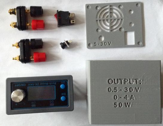
Bill of Materials:
- ZK-5KX or ZK-4KX (of course)
- 3D printed box from https://www.thingiverse.com/thing:5643934
- Rocker power switch
- 2x 2-way banana plug terminals
- 2.1mm DC socket
- Connecting wire
- 6-36V DC power supply
See the photo below and on the thingiverse link for more details of the additional components required.
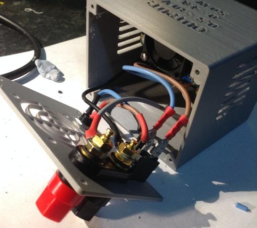
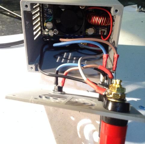
Building it was a bit fiddly, just getting everything connected. I used spade/ring crimp connectors, just soldering between the power IN socket and the switch.
To connect to other things I picked up a range of banana plugs. The “quick release” ones at the top of the photo are particularly useful.
Initial Testing In Use
Well in general it appears to work. But there are some, well really they are bugs, in the UI that are a bit annoying. Here’s what I’ve found so far:
- The soft power off/on (pushing the switched encoder) doesn’t work after using the encoder to dynamically change the voltage. Going through the “UI” selection seems to wake it up again.
- Dynamically changing the voltage whilst on also changes the preset setting, so power off and on will return to the adjusted setting not what was originally stored (I can sort of see why this might be useful).
- You can only see one of the OUTPUT voltage, INPUT voltage or the temperature reading at once.
- When showing the INPUT voltage or temperature the encoder will still change the OUTPUT voltage – but you can’t see it!
- The “UI” selection to change the pre-set voltage or current limit is quirky to say the least. It starts with the 2nd least significant digit on the display selected which for voltage means changing 0.1V and for current means changing 0.01A. But the up/down spills over so for example, changing the current that is set to 0.800 goes as follows:
- Up: 0.810, 0.820…0.890, 0.900.
- Down: 0.800, 0.790…
- … but this takes effect from whichever digital is selected, so pressing the encoder to change from the 2nd from last digit to the 3rd from last, and starting from 0.800 goes:
- Up: 0.900, 1.000, etc
- Down: 0.800, 0.700..
There is some discussion on the Internet that the current limiting doesn’t kick back in after a software on/off (i.e. pushing the encoder switch) which of course could be a significant problem. But my unit seems to have a different issue. At no point did I manage to get the “CC” LED lit up, which I thought would be an indication of the current limiting kicking in.
Instead, whilst testing with a device that is supposed to require a 12V/1.2A power supply, I found the following:
Voltage SettingCurrent SettingVoltage ReadingCurrent Reading12V1A12V250 mA12V800 mA~3.3V~860 mA12V400 mA~2.4V~460 mAThis was a bit of a puzzler. It would appear that the current limiting was probably kicking in, but ~60mA above the limit that was set.
However, at a steady state, with no (or higher) limit, the device was running with a 250mA current draw at 12V. That should have been well within the 800mA and 400mA limits, yet they seemed to kick in for some reason. As this was a more complicated device rather than a simple load, I think I have to conclude that maybe there is a power spike of between 0.8A and 1.0A on power up with makes the limiter kick in. There has to be a reason, I guess, for the device requiring 12V/1.2A.
The next test used 6 LEDs each with a 160Ω resistor. In theory this should be drawing around (5-2)/160 = just under 20mA each, so around 110-120mA in total.
Voltage SettingCurrent SettingVoltage ReadingCurrent Reading5V1A5V~90mA5V50mA5V~90mA5V10mA5V~90mAOk, so if it is really 90mA then that implies 15mA per LED which would imply a Vf of around 2.4V, assuming the 160Ω resistors are accurate (but of course, they won’t be). But really the key result is that regardless of the current limit setting, in this case it seems to make no difference!
The next test used ten 100Ω resistors. These were 1/4W resistors, so I chose 100Ω so that at 5V that is 50mA giving 0.25W. With 10 of them that should be a total of 500mA with no other losses, etc.
Voltage SettingCurrent SettingVoltage ReadingCurrent Reading5V1A5V~390mA5V500mA5V~390mA5V200mA~3.3V~260mA3V200mA3V~250mA3V100mA3V~170mA3V50mA1.7V~145mA6V400mA6V~460mA6V200mA~3.1V~265mASo what can I conclude from this?
- Current limiting seems only really useful above ~100mA.
- It seems to actually limit at around 60mA above what the current limit is set at.
- I don’t believe I have the issue with the soft power on/off not invoking current limiting.
- I still don’t know what the CC LED is for. I’ve not seen it come on yet!
The 60mA over limit could be a calibration issue perhaps? There are ways of calibrating the unit but I’ve not looked into those yet.
I should add that every time I’ve measured the OUTPUT voltage it seems to have largely matched the stated OUTPUT voltage shown on the display. At least within a few 10s of mV, which again is probably something that calibration could correct if more accuracy is required.
One final observation – in all of this testing so far, I’ve not once seen the fan come on for the heatsink. I assume that is probably temperature dependent and during this initial testing, the few times I’ve actually checked, I’ve not seen the temperature reading rise above ~25°C.
Conclusion
As a general purpose power supply, I think the voltage output will be useful. The UI is a bit clunky but its serviceable. There are a range of protections built in that I’ve not explored.
I guess I believe I can rely on the current limiting as long as I’m setting it in the mid 100mAs with a decent voltage (say 5V+).
The most important thing will be NOT to plug anything in until I’ve powered it up and set the voltage and current correctly. If I use it regularly for the same thing, then it would be wise to fit a switch on the OUTPUT side to save constantly plugging and unplugging banana plugs!
Note – there is an option to have the unit power up with the “soft” power switch OFF, but given the comments online about current limiting, even though I don’t seem to have that issue, I’m not sure I trust it yet.
I’ve only done some initial messing around so far, so this has not been seriously used yet. But at this point I feel relatively confident using it when I need to properly power something up. I’ll probably use it on some other lesser important projects before letting it power a retro computer. I did let it fire up a RC2014 though and that seemed ok.
If I manage to melt something or blow it up, I’ll be sure to come back and make a note of the fact!
Kevin
#3dPrinting #currentLimiting #powerSupply #psu #zk5kx