I'm looking for #opinions from #electronics #hobbyists or professionals.

When I'm using a #solderless #breadboard to prototype circuits, resistors can be frustrating. If you just keep re-using the same well-worn ones that look like a pretzel, you have to leave the leads long for the unknown next place you want to use them, and you can accidentally short something else against the leads.

Over the years I've frequently thought "Someone must make #jumper wires with inline resistors so they're easy to reuse", but I've never seen them for sale. [1]

So I made a bunch. And wow, it's labour-intensive to make them well. That explains why no-one's selling them.

Would other people be interested in buying and using these? Anyone can make them, but a lot of people would rather use their limited #hobby time to make their projects, not make things they need to make their #projects.

I've reduced the amount of time to make them and will keep trying, but I would have to charge at least US $30 for a pack of ten. There are ways to reduce it further, but they require a significant investment in equipment, so I'd have to be selling quite a few.

I make them with good materials - silicone 26AWG #wire for flexibility, name-brand 1% metal film #resistors, total length 24cm.

Would anyone want these?

[1] Closest thing I've found is https://www.dfrobot.com/product-1438.html but they're rigid so you need to use an additional wire anyway if you're not connecting exactly that distance through clear space.

#DIY

Ich hasse kleine #SMD ICs.

1,6 x 1,6mm in einer #FritzBox 7590

(Stark vergrößert)

#elektronik #elektrotechnik
#löten #sot563 #soldering #solderless

I designed a #SMD adapter board using @kicad and let @aislerhq manufacture them. They are for #SOT23 on one side and #SOT363 on the other side. They bridge the gap of a #solderless #breadboard, so they are perfect for #prototyping circuits or trying out new components - or as replacement for through-hole parts. I soldered a dual diode #BAV70 on one and a dual NPN/PNP transistor #BC847BPN on a second one to try them out. I'm satisfied how they look, although the white area for labeling is a bit small - I need a thinner pen for that.
You can find the shared project here: https://aisler.net/p/UTAGNLYX (trying out this feature, please give feedback if you use it).
#diyelectronics #soldering #kicad #aisler
Nützliches / SOT-23 / SOT-363 by Rommudoh on AISLER

Nützliches / SOT-23 / SOT-363 by Rommudoh on AISLER

Just a brief #factoid to perhaps save other #electronics #hobbyists some time.

#BigClive frequently uses a particular type of crimp-contact-and-housing as a universal socket for LEDs and other leaded components. Not just any such connector will do; various #JST, "#Dupont", and others won't work, because they only grasp pins of one particular size and/or shape. If the lead is too big, it won't go in, and if it's too small, it won't stay in.

If you want to use these connectors - and note you can get the housings with more than 2 contacts, so you can use them for transistors or weirder things too - the magic search term is "KF2510".

The reason these work as universal sockets for leaded components is because the contact is a spring that pushes from only one side of the housing, pressing the inserted contact or lead against the far side of the housing, and therefore provides a friction fit for any size lead (within reason). Most crimp connectors instead have particular shapes for their contacts and will only "grab" something the right size and shape.

#KF2510 #CrimpConnector #crimp #socket #component #leaded #connector #solderless #universal #contact #housing

More #diysynth #prototyping on my #solderless #breadboard. This time, I try a 5 step #sequencer using a 4016 decade counter, and a #VCO using a 40106 inverting Schmitt trigger.

IAttached them to my ADSR and VCA for testing them.

For perfboards, I'll make it a full 10 step sequencer with configurable reset, for 1 to 10 steps. And since the inverting Schmitt trigger comes in packages of 6, I'll make it a multiple, too. Maybe 3-4, depending on available space.

Demo video: https://makertube.net/w/a5NqkQhVuj5TaXKzLbNwRF

Sequencer and VCO prototype

PeerTube
Switching Converter For EEPROM Programmer Taxes Solderless Breadboard

We all know that solderless breadboards have their limitations. All that stray capacitance can play hell with circuits, especially high-speed stuff, but they’re so darn useful that avoiding t…

Hackaday

Has anybody ever used neoprene prototyping boards? How well did they work? Anybody still selling those? (Add is from the early 80s).

I've used point to point, wirewrap, veroboard, protoboard, breadboard, deadbug, flipped wirewrap, and even conductive ink, but never seen or used this technique of neoprene (compression) prototyping.

#electronics #diy #maker #circuits #prototyping #solderless

Circuit Candy Hearts

Irreverent electronics and frivolous circuits with a feminist bent. We want everyone to enjoy learning about electronics!

Alpenglow Industries

Keebin’ with Kristina: the One With the Tri-lingual Typewriter

Isn't it just fantastic when a project finally does what you wanted it to do in the first place? [Simon Merrett] isn't willing to compromise when it comes to the Aerodox. His original vision for the keyboard was a wireless, ergonomic split that could easily switch between a couple of PCs. Whereas some people are more into making layout after layout, [Simon] keeps pushing forward with this same design, which is sort of a mashup between the ErgoDox and the Redox, which is itself a wireless version of the ErgoDox.

The Aerodox has three nRF51822 modules -- one for the halves to communicate, one for the control half to send key presses, and a third on the receiver side. [Simon] was using two AA cells to power each one, and was having trouble with the range back to the PC.

The NRFs want 3.3 V, but will allegedly settle for 2 V when times are hard. [Simon] added a boost converter to give each a solid 3.3 V, and the Aerodox became reliable enough to be [Simon]'s daily driver. But let's go back to the as-yet-unrealized potential part.

The point was to use this keeb on multiple PCs with ease. [Simon] recently found someone's Bluetooth code for the Mitosis keyboard and adapted it to work on the Aerodox. He's using a Gazell link between the halves, and Bluetooth from the control half back to the PCs. Unfortunately, [Simon] had to revamp the timer interrupts and debouncing scheme that came with emulating the Redox, but it works now and it switches between PCs with the press of a button. Now that [Simon] is nice and comfortable with nRF silicon, we might see an nRF52 version running ZMK next. Time will tell.

Historical Clackers: Tri-lingual Toshiba Typewriter

Image via This is Colossal

No, that isn't an ornate roll-top desk -- it's a tri-lingual typewriter made by Toshiba from 1940-1954 with over 1,000 characters. This bad boy can type in Japanese, Chinese, and English by spinning the cylinder, using the pointer to select the character, and working the lever down below.

This is the second index typewriter that Toshiba produced. The first was called the Nippon, and came out in 1915. The Nippon worked by selecting an individual character from a tray. In the mid-1950s, Toshiba switched to a Western-style keyboard.

On this one, the BW-2112, the kanji are arranged phonetically down the long edge of the barrel, and the Arabic letters and numbers are in alphabetical and numerical order. As you might guess, it's a pretty slow process, even if know what you're doing. But you don't have to guess what that looks like -- just check it out in the video below. Too bad we don't get to see the inside.

Thanks to [ukezi] for the tip on this one!

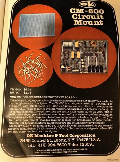
ICMYI: Look Ma, No Solder

Do all these crazy inputs make you want to jump in the keeb game? That's totally understandable. So why not start small?

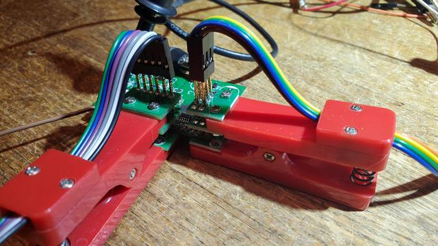
With 3D printers around, it really couldn't be any easier to build a custom macropad, especially when you have the shoulders of hackers like [Jan Lunge] to stand on. And with [Jan]'s build, you don't even need any solder.

The key to connectivity here is in the small plastic clip [Jan] designed that snaps in after you've run the column wire. Not only does this plastic bit keep both wires held in place, it keeps them separated, too -- this is especially good if you plan to use bare wire like [Jan] did.

With a design like this one, it would be easy to dress it up with color, or make it minimal and monotone. Either way, it's sure to look nice on your desk.

Got a hot tip that has like, anything to do with keyboards? [Help me out by sending in a link or two](mailto:[email protected]?Subject=[Keebin' with Kristina]). Don't want all the Hackaday scribes to see it? Feel free to [email me directly](mailto:[email protected]?Subject=[Keebin' Fodder]).

#hackadaycolumns #peripheralshacks #aerodox #bluetooth #ergodox #macropad #nrf51822 #redox #solderless #solderlesscircuits

Keebin’ With Kristina: The One With The Tri-lingual Typewriter

Isn’t it just fantastic when a project finally does what you wanted it to do in the first place? [Simon Merrett] isn’t willing to compromise when it comes to the Aerodox. His original v…

Hackaday

Who Needs Pin Headers?

[Martin] sent this query, along with the lead photo, into the tip line, and he makes a good point. Most development and evaluation boards have multiple rows of pin headers, often arriving loose in the package -- soldering is left to the user. In an abundance of caution, we usually design our prototype boards with many pin headers for debugging and testing. But as [Martin] reminds us, there are other alternatives to solder.

  • Yours truly once worked with a prolific designer of PIC microprocessor boards. Long before the advent of solutions like the Tag Connect family, [Ralph] would program his boards by just inserting a pin header into the PCB and applying gentle pressure with his thumb until the code finished flashing.
  • You may have seen the staggered offset PCB patterns that hold your pin header securely while you solder. You could tweak this a little bit to put more pressure on the pins, making a solder-less connection that is sufficient for temporary testing.
  • Taking the opposite approach, you can get solderless connectors with press-fit pins, a method we tested a few years ago on a Raspberry Pi Zero. Anyone who has worked on Eurocard-based systems like VME can appreciate the time-savings and improved reliability of 96-pin DIN-41612 press-fit connectors.
  • Or, as [Martin] proposes, you could use one of these inexpensive pogo-pin clamps. These are available for less than $10 from your favorite Asian electronics distributor. They are about the size of a large clothespin, and are available in several different pin configurations.

These techniques won't help you if you need to plug your board into another card, such as a hat onto a Raspberry Pi. But when you just want to grab a few signals for a serial port or probing some digital I/O signals, having a few of these clips in your tool box can save you the time and headache of soldering down a header. Do you have any tips for making soldering pin headers easier, or even avoiding them altogether? Let us know in the comments below.

#hardware #techhacks #pinheaders #pogoclamp #pogopins #solderless

Who Needs Pin Headers?

[Martin] sent this query, along with the lead photo, into the tip line, and he makes a good point. Most development and evaluation boards have multiple rows of pin headers, often arriving loose in …

Hackaday