Simple PWM Filter PCB Build Guide
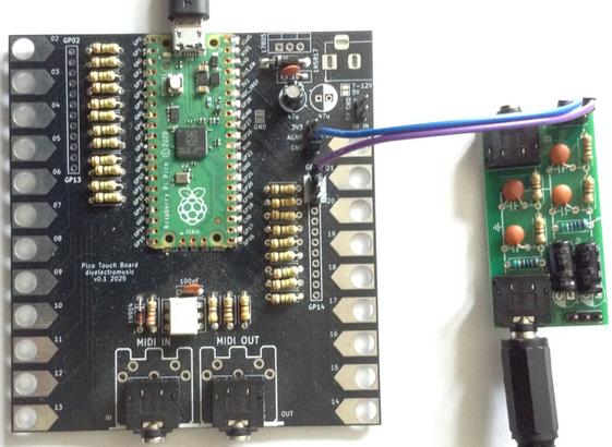
Here are the build notes for my Simple PWM Filter PCB Design. Below you can see it connected to my Pico Touch Board.
Warning! I strongly recommend using old or second hand equipment for your experiments. I am not responsible for any damage to expensive instruments!
If you are new to electronics and microcontrollers, see the Getting Started pages.
Bill of Materials
- PWM Audio Filter PCB (GitHub link below)
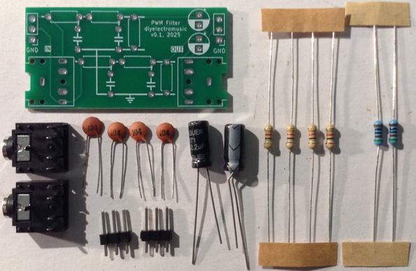
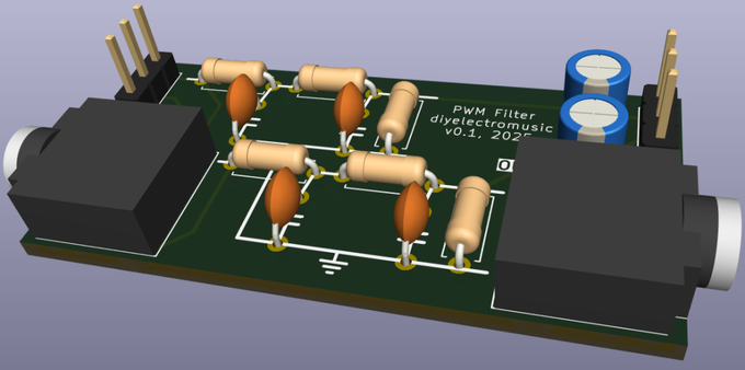
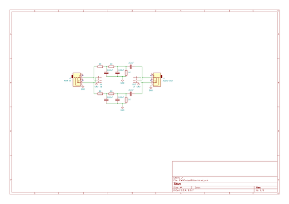
- 2x Suitable filter components, for example, per channel:
- 3x 1KΩ resistors
- 2x 100nF ceramic capacitor
- 1x 2u2 electrolytic capacitor
- Optional: Pin headers
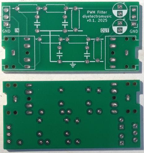
- Optional: 2x 3.5mm TRS sockets (pcb mounted, see photos for footprint)
Build Steps
Taking a typical “low to high” soldering approach, this is the suggested order of assembly:
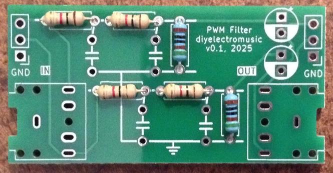
- All resistors.
- TRS sockets (if used).
- Disc capacitors.
- 3-way jumper headers (if used).
- Electrolytic capacitors.
Here are some build photos.
If the electrolytic capacitors will be bent over, then they should be bent and soldered in place before the header pins.
Testing
I recommend performing the general tests described here: PCBs.
PCB Errata
There are no known issues with this PCB at present.
Enhancements:
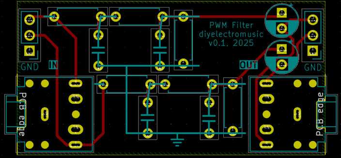
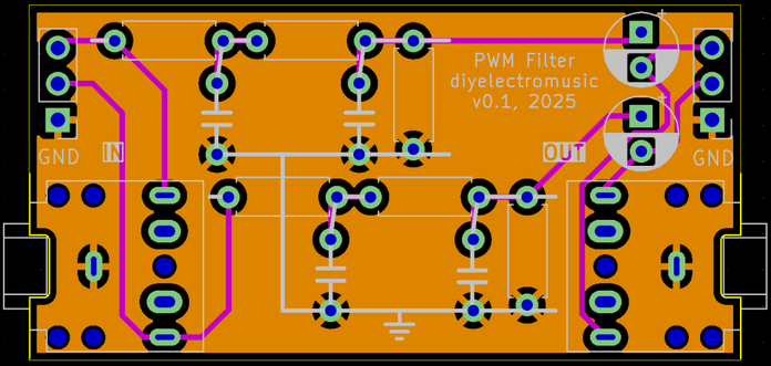
- As previously mentioned it might have been useful to label the left and right channels and use the alternative resistor circuit symbol.
- It might have been useful to include solder jumpers to allow the simple combining of the left and right inputs and outputs
- Some additional connection points for an oscilloscope might have been useful too.
Sample Applications
Here are some applications to get started with:
- Pico Touch Board Audio – 3x 1K resistors, 3x 100nF capacitors, and 1x 2u2 electrolytic per channel.
Experimenter board
Rather than fixed components, it is possible to solder on round pin header sockets to allow components to be pushed into place. This means that it is fairly easy to experiment with alternative component values to see what difference they make.
When doing this, I only soldered up one channel, but joined the left/right inputs and outputs by adding a solder bridge across the pin headers. I also soldered additional pins to the spare GND connections from the second channel. This allows plenty of pin connections for an oscilloscope.
The connections for components aren’t as tight as they could be, especially for low-wattage components with pretty thin legs.
It might be that just continuing to use solderless breadboard for experiments is simpler, but it was pretty useful to be able to leave oscilloscope connections and the input and output connected whilst experimenting.
Board Manufacturing
These boards are sized to allow them to be ordered in a 2×4 panel if required, and still remain within a 100x100mm footprint. I used jlcpcb’s panel options with v-cuts and it was really quite inexpensive to do.
Closing Thoughts
I’m still not sure I really understand enough analog electronics to get the theory of how a dual-stage filter incorporating a potential divider still works, and any simulation is still not quite matching my theory to experiment.
As has been said, “in theory, theory and practice are the same, in practice they are different”.
This might make some proper practicing a bit easier.
Kevin
