Philip Bragg

@synx508@bsd.network
325 Followers
419 Following
2.8K Posts
Mostly electronics and all sorts of synthesizer, he/him.
Websitehttps://mossyvale.co.uk/
Bluesky@synx508.bsky.social
I have rebuilt my Inovonics 222 clone on copper clad board instead of annoying stripboard
Byron
The descriptions on ebay get weirder, thanks to the "AI". Here an old HP CW sweep generator is described as a cow generator and is here to generate electricity from manure, or something? https://www.ebay.co.uk/itm/336025379743
Newbury Radio Rally is not going ahead because of roadworks. Bah!
Elsinør had a sleep on an HP 8903B recently. She loves to flop her head down from resting places. #Catsofmastodon
Another HF site with microwaves that are likely pointing at Buckingham Avenue. This year’s McMichael radio rally will be in this field. Hmm!
It is one of those pretty translucent boards
Send it any character and the GPIB responds with lots of ASCII 1s and 0s. The pattern is different if the output switch on the front panel is switched between On and Off. I haven't managed to guess the commands to set a voltage or current limit yet. I've tried the obvious characters already.
The third item of test equipment from the rally was this Farnell 30V 2A GPIB programmable PSU for a fiver. Earlier tests showed the output was hunting around a bit when lightly loaded, this turned out to be a missing sense line shorting strap on the back panel. Just needs feet and to figure out GPIB commands. Do you know them?
I got it working! I wasn’t expecting to, particularly after a silly accident this morning that saw me toast many of the parts I had just fitted.to the RF amplifier. Definitely need to dim the green LEDs! 2f is better than specification.
×
The third item of test equipment from the rally was this Farnell 30V 2A GPIB programmable PSU for a fiver. Earlier tests showed the output was hunting around a bit when lightly loaded, this turned out to be a missing sense line shorting strap on the back panel. Just needs feet and to figure out GPIB commands. Do you know them?
Send it any character and the GPIB responds with lots of ASCII 1s and 0s. The pattern is different if the output switch on the front panel is switched between On and Off. I haven't managed to guess the commands to set a voltage or current limit yet. I've tried the obvious characters already.
Update:
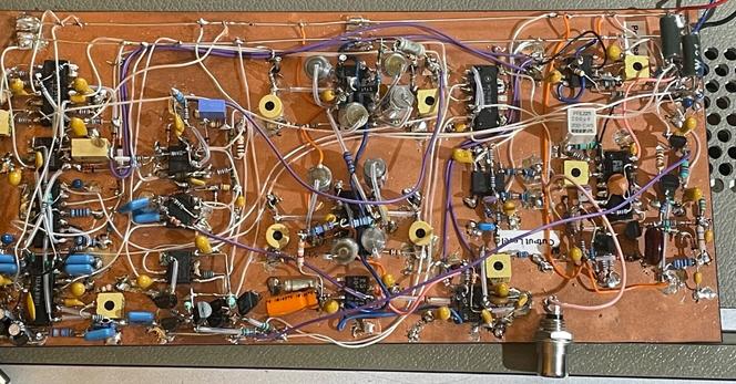
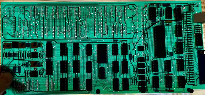
The IC that I'd assumed was a microcontroller is a dedicated IEEE488 controller from Philips, HEF4738VP. It deals with the GPIB bus prototol can delivers (or consumes) a series of bytes from a simple 8 bit bus in the instrument. This takes the form of a counter, some gates and a 1-of-16 decoder, some more gates, 6 4-bit latches and two 3.5 digit BCD programmable potentiometers that have their MSD tied to a logic 1, so they're only 3 digit. All I need to do is figure out how the logic mangles an incoming stream of bytes in order to fill all the latches. There is no readback - the section of the PCB where this could be implemented is entirely unpopulated, so it's write only - which is curious as it's emitting 1s and 0s randomly when addressed on the GPIB. Every IC is in a cheap socket, which might make it easier…
It is one of those pretty translucent boards
There is, in fact, one bit of readback. I'm not sure what it means yet but most likely it is an indication if the PSU is operating in CC or CV mode.
The logic was giving me a headache so I identified the key parts of the state machine, and how the digits were clocked through to the DACs which then enabled me to monitor a specific line while typing letters and numbers at it from a terminal session. The programming string for voltage is VxxxP where xxx is a between 000 and 999. 999 sets the output to 30 volts.
Programming current is similar, IxxxP where 000 is 0mA and 999 is the full current capability, a little over 2A
Typically I've been distracted and now though I know those two commands I also now know that there must be another command because from a cold start I can't get it to do anything!
Scrollback to the rescue, sort of, I pasted the nonsense I'd been typing to brute force it and now it's working again. One of the characters or perhaps more than one, in that mess is the key!
Readback bit is 0 for constant voltage and 1 for constant current mode.
Looks like I have made an error and the P isn't required, but I know P causes the state machine to reset so it must be important. Hmmm
The missing link is C. I still don't know why. P does a reset, so it's best to start with that, I suppose. A complete string would be PV999I999C
That programs the supply from cold (it has no NVRAM so it doesn't remember settings)
As well as B there is C, which is the opposite of B. Maybe break/connect? Unsure, anyway, C turns on and B turns off. Neither really does a disconnect as there doesn't seem to be a relay in there, it just drops to 0V
S and R have a similar effect, set and reset? Probably just the same LSBs.
@synx508 It almost smells like serial (at a much lower baud rate)?!
Have you tried sending a '*IDN?' (I'm not sure if HPIB needs a linefeed after that or not)
@penguin42 I didn't because I've a feeling that SCPI is a fair few years newer than the power supply. Will have another look tomorrow.
@synx508 wow no sign of this online, that I can find. I'd start with sending it "outp on" and see what that does, but given its age it may use purely cryptic alphanumeric commands
@smellsofbikes My old Thurlby Thandar was easy to guess, It was a dual PSU and it used V<PSU number><voltage>. No such luck with this, though. It has what looks like a single chip 40 pin MCU, but I don't recognise it and I doubt the code can be read. If it was just on a ROM/EPROM it would be a bit easier.