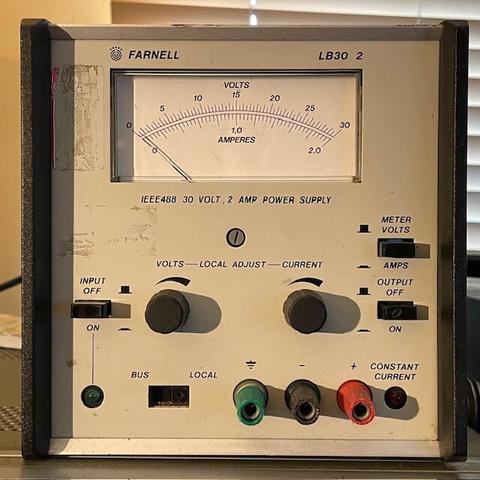
The third item of test equipment from the rally was this Farnell 30V 2A GPIB programmable PSU for a fiver. Earlier tests showed the output was hunting around a bit when lightly loaded, this turned out to be a missing sense line shorting strap on the back panel. Just needs feet and to figure out GPIB commands. Do you know them?
Send it any character and the GPIB responds with lots of ASCII 1s and 0s. The pattern is different if the output switch on the front panel is switched between On and Off. I haven't managed to guess the commands to set a voltage or current limit yet. I've tried the obvious characters already.
Update:
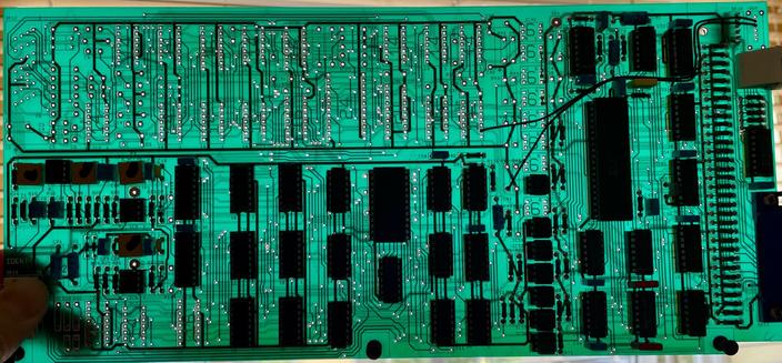
The IC that I'd assumed was a microcontroller is a dedicated IEEE488 controller from Philips, HEF4738VP. It deals with the GPIB bus prototol can delivers (or consumes) a series of bytes from a simple 8 bit bus in the instrument. This takes the form of a counter, some gates and a 1-of-16 decoder, some more gates, 6 4-bit latches and two 3.5 digit BCD programmable potentiometers that have their MSD tied to a logic 1, so they're only 3 digit. All I need to do is figure out how the logic mangles an incoming stream of bytes in order to fill all the latches. There is no readback - the section of the PCB where this could be implemented is entirely unpopulated, so it's write only - which is curious as it's emitting 1s and 0s randomly when addressed on the GPIB. Every IC is in a cheap socket, which might make it easier…
It is one of those pretty translucent boards
There is, in fact, one bit of readback. I'm not sure what it means yet but most likely it is an indication if the PSU is operating in CC or CV mode.