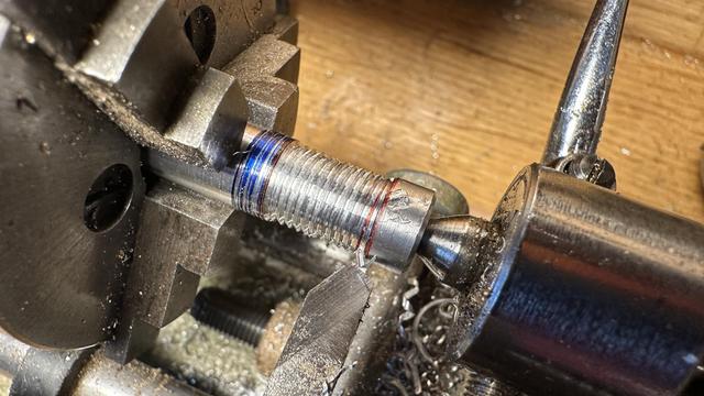
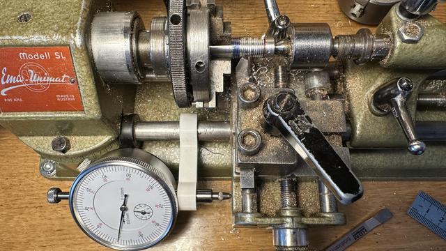
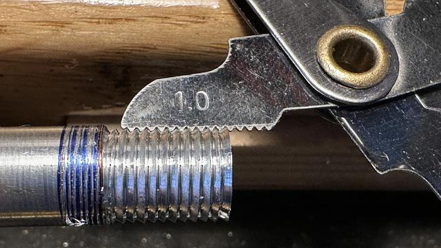
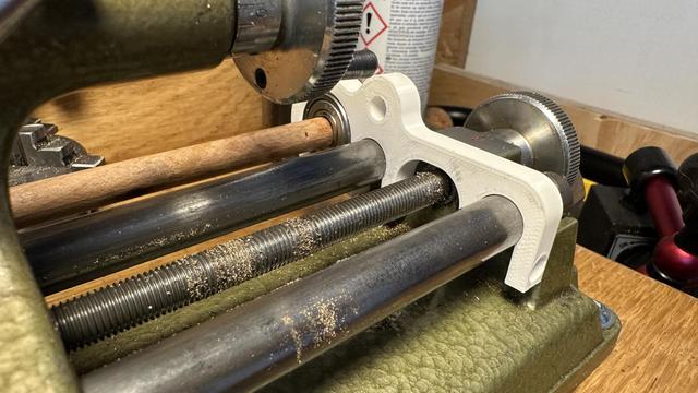
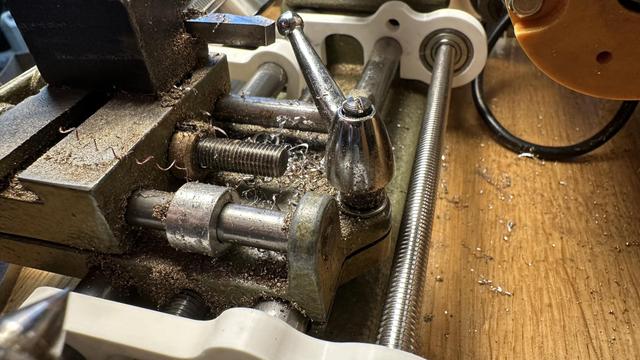
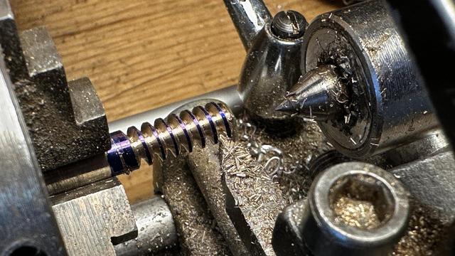
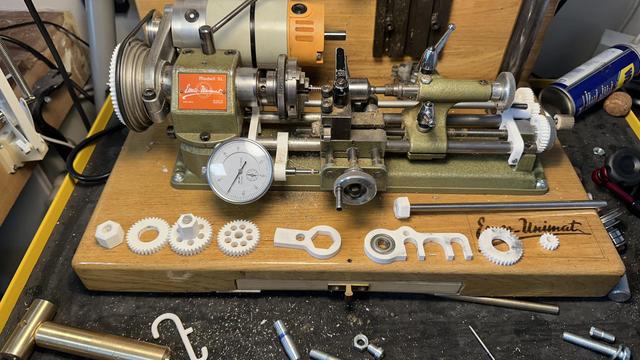
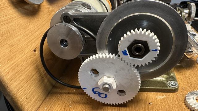
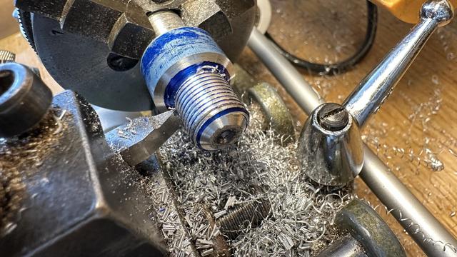
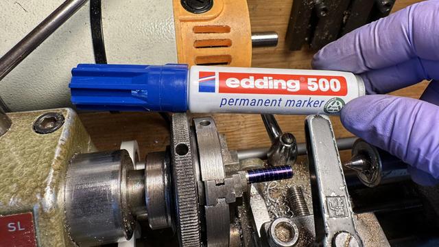
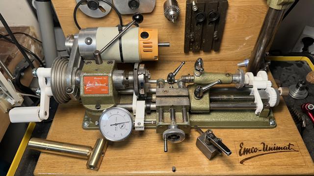
Trying my hand at manual single point threading without change gears or a powerfeed.
3D printed end stop and carriage position indicator make it possible to return to the same starting location.
Turning the spindle and the carriage feed at the same time by hand produces a 1.0mm thread.
Drawing the gear train and mount for the thread cutting attachment really makes me wish FreeCad allowed text notes in sketches.
Printed bracket is pretty close to right -- the fitting on the ways is good and tight, but the bearing is slightly too close and the shaft (a temporary wooden one right now) impacts the carriage.
Version two has just enough space for the carriage lock while not hitting the spindle belt or motor housing. Like Quinn says, "clearance is clearance"... time to print some gears.
All of the thread cutting attachment parts are modeled; it is now just a matter of waiting on the printer to finish making them and tracking down a long enough 8mm axle for the cross shaft.
First set of gears just barely fits for cutting a 2.0 thread pitch (60:30 ratio and one turn of the hand wheel is 1 mm of carriage travel)
Hopefully making chips soon! I've acquired an 8mm axle so I need to re-print the pieces that were threaded onto the temporary test shaft, along with grub screws to hold them in place.
M6x2.0 test cut is mostly a success! This is not a standard size, but works with the 30:60 ratio that I had printed for the first set of change gears.
The lathe threading attachment is not very rigid, so I can only cut 0.1 to 0.2mm per pass, and the gear train is really high friction, but that's a really small number of test prints for me on a project of this complexity.
Turns out there is almost no friction in the gear train, if I remove the belt from the lathe motor. It almost as it is acting as a weak electronic brake... I'll have to add that to the README
With two 45 tooth gears mounted, the lathe will cut 1mm threads, which let me make a custom M12x1.0 extra fine pitch mounting screw for the spindle and tailstock accessories.
The blue is a marker pen and washes off easily with isopropyl. During the threading operation it shows the parts that have not yet been cut and on the first pass lets me double check the pitch before committing.
I've added a crank to the change gear to make the lathe spindle easier to turn by hand while cutting threads and am ready to call the design complete. Now for the hard part: committing the files and writing the blog post.
My FreeCAD design and STL files for the 3D printed attachment to cut threads on the Emco Unimat SL manual micro-lathe: https://trmm.net/thread-ripper/
Thread cutting on an Emco Unimat micro-lathe

This is a 3D printed thread cutting attachment for the tiny Emco Unimat SL manual lathe.

Trammell Hudson's Projects
@th ``Threadripper.''
@th Hey, awesome work, I kinda want to do this to my unimat 3 now, although that's a stalled partially CNC converted project... Anyway.. this is awesome, I'd love to feature it on the main FreeCAD blog if you are up for that?
@th also notes in sketches... that's a great feature request. I tend to use the project wide "Tools > Text Document" but am aware it's not what you are really looking for.
@th M6x2.0 is a worm gear not a screw. 😂
@th Well, 30° pressure angle would make a rather bad worm gear I think. So maybe it's just a fun test screw. 🤷
@th i see a bunch of scary pinch points here but i bet a lathe has plenty of finger eaters even before you start adding stuff
@th this is pretty amazing 😯

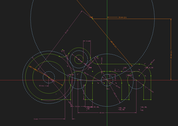
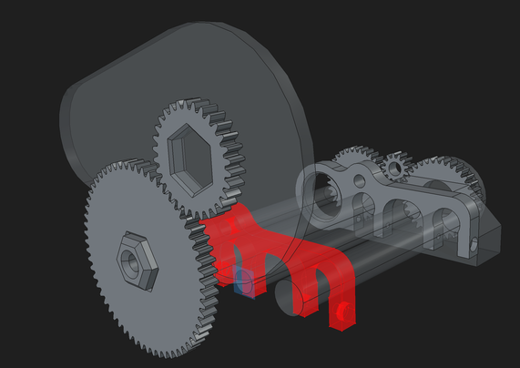
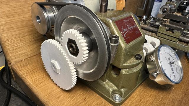
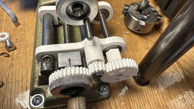
@th Why did you choose spur gears instead of double helical?

I far as I know the spur gears are less sensitive to misalignment, but aligned with precision double helical have much less backlash.

Btw, some people recommended me to print gears from PET rather than PLA since PET is more soft and forgiving for misalignment.

@th ...

...

...

...

... Clarence.

@th I dont have the full context but it seems that this sketch contains too much information, it already plans for mechanical functions I would add later, like holes and fillets.
@f4grx my experience thus far with FreeCad is that adding holes and radiuses later guarantees topological naming problems when I change the sketch and those faces get renamed so the chamfers or filets no longer are attached. Including them in the sketch ensures that I have a single-point-of-truth for the positions and sizes of everything as well; I find the tree hides these relationships where a drawing reveals them.

@th I understand this approach. Specifically if gears are involved it's inevitable that you need similar reference lines in many sketches.

The trick with freecad topological problems is to draw sketches not on faces, but on reference planes aligned with those faces. This solves 99% of the problem.

edit: fillets are a pain I agree. I leave them as last steps when I can.

@f4grx yeah, I've learned that the hard way, too. It would be nice if you could name edges in sketches so that those edges would be consistent. I'm 3D printing these pieces, not machining them, so the order-of-operations doesn't need to make sense for a subtractive mill.

@th That was the context I was missing :)

I agree with you on edge naming. But not sure these would be stable with the topological problems.

@f4grx my preference would be to have close to everything on one sketch, like a proper engineering drawing. If the Hole tool allowed notations for "this is tapped M3, this is a clearance M8 countersink" then the hole pattern could also be on the same sketch referencing the same points. And if the Pad tool allowed notation for "this region is 5mm thick, that region is 10mm" and "chamfer the result of this extrusion" then it would also reduce the number of duplicate reference lines and ops.

@th @f4grx Basically the inverse of TechDraw?

I think that a practical current problem with this is that the 2d sketch solver has two characteristics that would get in the way, and which would need to be addressed to make that practical.

When dimensions change significantly, it sometimes "flips" into nonsense shapes. It's easy for me to say "just maintain the topology and never choose a solution that changes the number of crossings" but I don't think it's that easy to implement, or it would have happened already?

The sketch solver does bog down when there are a lot of constraints, especially when they stack.

(I've learned to dimension as much as possible from the origin of a sketch, including formulas, when I'm making a necessarily complex sketch, in order to make it stable in the face of parametric change and faster to compute.)

I've pondered whether a "CadQuery Workbench" could make sense. The power of CadQuery for stable construction with the convenience of building things in a visual UI instead of having to hold mentally the entire mapping of code to complex object. 🤔

@th you can use labels from the draft workbench to insert custom text or have calculated values like area, length, volume, etc, but it is a clunky feature to use and its placement is fixed, so if you resize a drawing, it remains pointing to the same point in space from before. You can select edges, vertices, faces or entire objects with it, just gotta deal with the different snap buttons of the draft workbench.