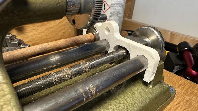
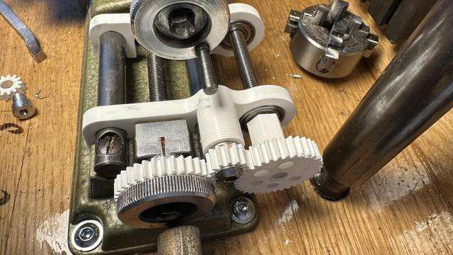
Printed bracket is pretty close to right -- the fitting on the ways is good and tight, but the bearing is slightly too close and the shaft (a temporary wooden one right now) impacts the carriage.
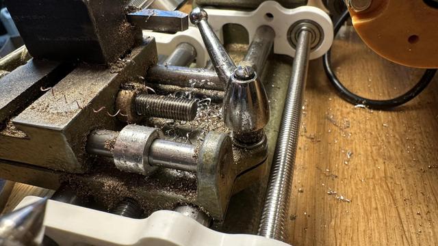
Version two has just enough space for the carriage lock while not hitting the spindle belt or motor housing. Like Quinn says, "clearance is clearance"... time to print some gears.
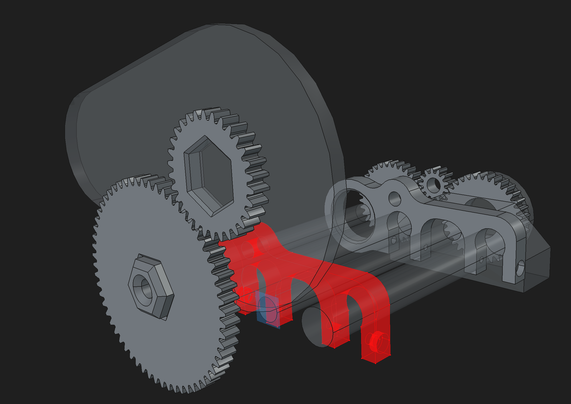
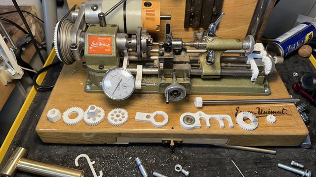
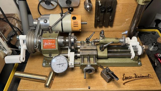
All of the thread cutting attachment parts are modeled; it is now just a matter of waiting on the printer to finish making them and tracking down a long enough 8mm axle for the cross shaft.
Hopefully making chips soon! I've acquired an 8mm axle so I need to re-print the pieces that were threaded onto the temporary test shaft, along with grub screws to hold them in place.
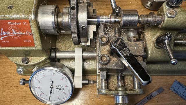
The lathe threading attachment is not very rigid, so I can only cut 0.1 to 0.2mm per pass, and the gear train is really high friction, but that's a really small number of test prints for me on a project of this complexity.
Turns out there is almost no friction in the gear train, if I remove the belt from the lathe motor. It almost as it is acting as a weak electronic brake... I'll have to add that to the README
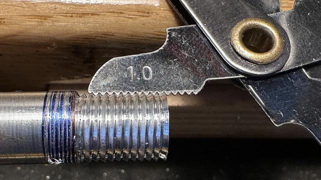
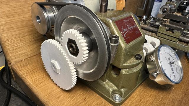
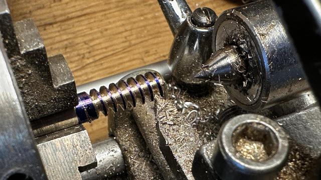
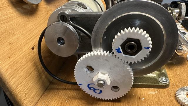
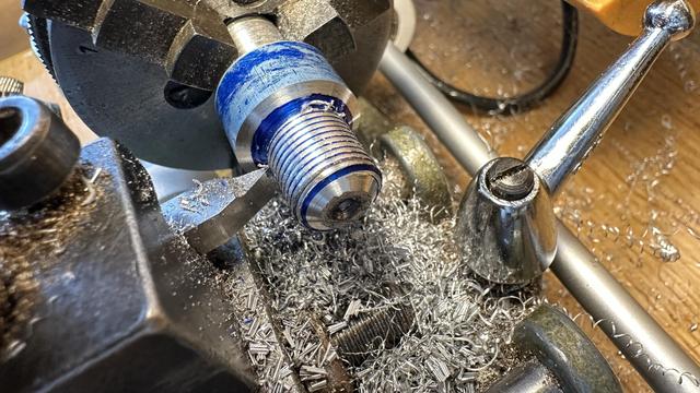
With two 45 tooth gears mounted, the lathe will cut 1mm threads, which let me make a custom M12x1.0 extra fine pitch mounting screw for the spindle and tailstock accessories.
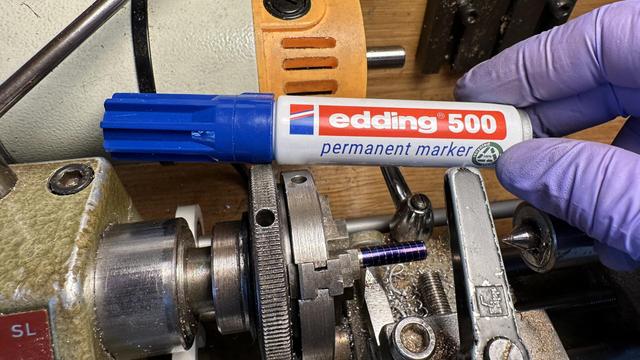
The blue is a marker pen and washes off easily with isopropyl. During the threading operation it shows the parts that have not yet been cut and on the first pass lets me double check the pitch before committing.
I've added a crank to the change gear to make the lathe spindle easier to turn by hand while cutting threads and am ready to call the design complete. Now for the hard part: committing the files and writing the blog post.
@th Hey, awesome work, I kinda want to do this to my unimat 3 now, although that's a stalled partially CNC converted project... Anyway.. this is awesome, I'd love to feature it on the main FreeCAD blog if you are up for that?
@th also notes in sketches... that's a great feature request. I tend to use the project wide "Tools > Text Document" but am aware it's not what you are really looking for.
 Trammell Hudson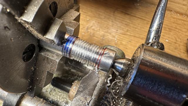

 Khleedril
 concretedog
 Cassandrich