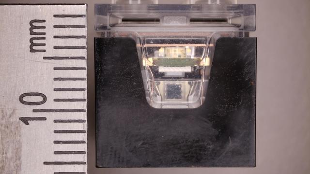
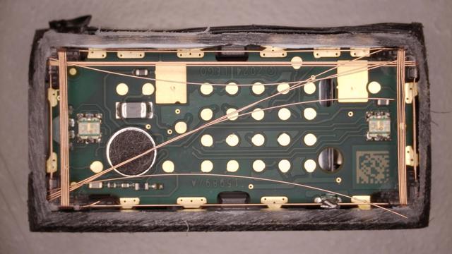
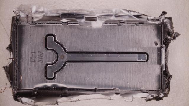
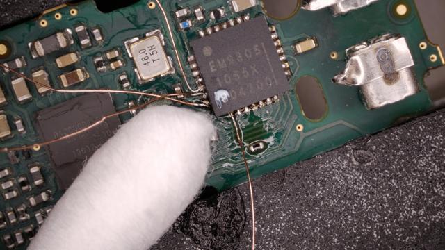
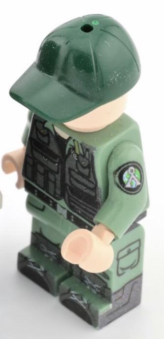
first impressions of the Lego smart brick, before I do any actual tearing down: wow, I forgot how good they are at working with plastic. the injecton molding remains impeccable, at least for this specific piece (I know about their recent QC issues elsewhere)

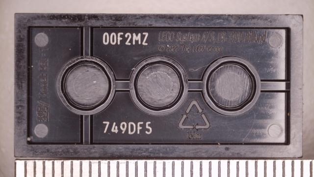
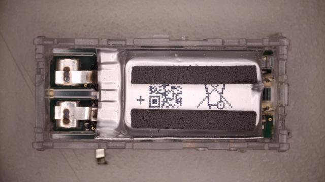
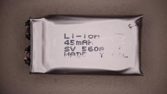
it's hard for me to look at the positively microscopic (I am literally using a microscope to look at it) "Li-Ion" lettering and think of anything but "showing off!"

(treehouse doesn't let me attach the full size images, you can grab them here: front, side)

on the side, there are microscopic openings for the speaker to move air through. I would have really liked to be a fly on the wall in a meeting with the mold engineer who had to make this happen

original

I'm not yet sure how I'll open it up. I don't have a hacksaw (somehow... I should fix that), so my options are somewhat limited: it's either cracking or melting plastic. from what others have done I know I there's plastic welding all around the joined region.

okay I've decided on an idea: I will heat up the plastic to make it pliable and then cut it with a knife

as a knfe girl, this is my professional obligation.

here's a video that shows in more detail the moldwork in the transparent plastic part
if you've never heard of anybody opening welded plastic this way, i can now tell you why: because it's a bad idea. until you heat ABS to the point where it flows (which you don't want here, as it'll make later teardown even worse), it acts rubbery. imagine cutting hot rubber. doesn't work

it did however let me lop off the top of it easily

this is I think a 2.4G antenna?

next step is sanding

yep that did the thing. probably should've started with sanding at the beginning.

it was somewhat more destructively than i wanted, but that's ok: i was trying to challenge my (incorrect) belief that sanding is always a tedious pan in the arse

took it apart. there's a sort of a plastic "carrier" that gets manufacured first, then inserted into the final package that's welded shut
okay, i've extracted the firmware-bearing parts. this is a tiny 45 mAh battery. (part of the lettering was torn off by the glue it was attached with)

close-ups of the component side (well, the side with more components)

originals: 1 2

EM9305 is an em|bleu microcontroller in QFN
it has over half a megabyte of flash!
ok so this would be the JTAG pins
also, here's a close-up of the markings on the tiny WLCSP between the BGA and QFN

decided the next thing to do would be to dump the presumed Winbond flash WLCSP

here it is mounted on a SOIC-8 pinout with a tiny bit of UV epoxy, like a particularly exotic dead bug

connected half of the pads

this is my first time soldering a 0.3mm pitch WLCSP, so it took me a bit to set up the workspace the way that makes it possible, but it's not too bad

finally done. no shorts and (as far as i can tell under mag) no opens
complete success
contrary to everything i've seen online, this is a Winbond W25Q16JWBY part (but one person got the closest, they thought it is a W25Q16JVBY. the difference is major: one is 3.3V, the other is 1.8V)

NotImplementedError: quad enablement SFDPJEDECQuadEnableRequirements.Reg2Bit1_Read35h_Write05h not implemented yet

ah yes. i remember why i hate SPI flashes now

tried using dual mode and the SFDP tells me to transmit half a byte

once i dump it this flash is definitely going into the naughty pile (of unit tests in glasgow)

here's how the flash was mounted in its natural environment, in absence of feline predators

the SPI bus seems to be shared with something else & they're definitely using ViP

alright let's dump the ARC chip now

not my best work but it should do the trick

feat. comically big q-tip

unfortunately, i could not access JTAG. i think i ran out of time i have for playing with this board, good luck @ everyone else

shout out to:
https://github.com/nanash1/smart_brick
https://codeberg.org/shelfofsheelfs/SMART-Brick
for doing good work!

GitHub - nanash1/smart_brick: Lego Smart Brick reverse engineered schematic

Lego Smart Brick reverse engineered schematic. Contribute to nanash1/smart_brick development by creating an account on GitHub.

GitHub
after reading the datasheet a bit more carefully, i know why i couldn't: the JTAG port is simply not exposed unless the firmware configures the pin mux that way. i'd have to dump the firmware in some other way
@whitequark oh how fun, but makes sense for such a pin-constrained device. Is there any other way to access it or is the chip just impossible to reprogram it if it doesnt expose JTAG?
@cinebox it has a bootloader which I assume is how it's programmed by LEGO; I think I know how to trigger that but I just wanted to connect JTAG because it was more challenging to solder these tiny wires and I'm bad at doing it
@whitequark could it have booted in cJTAG mode?
@ldcd the datasheet explicitly says the JTAG pins are GPIO'd

@whitequark yup i only mention because TMSC (GPIO11) and TCKC (GPIO10) both go straight to vias (and then maybe to the array of testpoints on the back?); Wheras TDO (GPIO9) seems to go to the flash and TDI (GPIO8) seems to go ??.

So I was thinking there's a chance they might be explicitly configuring it as cJTAG and using it for a boundary scan test after manufacture.

@whitequark if the REd schematic is to believed TCKC goes only to a testpoint
@ldcd hm it's possible but i haven't implemented cJTAG yet so can't easily test
@whitequark yeah it's a PITA I was trying to bring up a CC1354 and just could not get it to respond
@ldcd welp

@whitequark in theory you can use openocd to wake it up and switch it to 4 wire mode but thats also not very fun;

in the TI parts the GPIO mux is subordinate to the JTAG TAP so if you wake up 4 wire mode it takes over the other two pins no matter what the GPIO mux is set to afaict

@whitequark Just in case this were really the end... would you give away your PCB in the state it is right now? And maybe some advice how to dump it? I guess you mean the configuration mode thingie?
@maehw I am open to giving it away; I might consider doing a little bit more of RE work e.g. to probe if maybe the LEGO ASIC has a JTAG port available
@whitequark I won't stop you doing more RE'ing! Just curious if the internal flash could still be dumped and before it goes to the trash. Even though I may be lacking the skills to do so.
@maehw ah I don't trash boards like that unless I 100% know there's nothing more to be gained from them
@whitequark oh lol I thought it was a cat’s paw
@dev that would be a really small cat

@whitequark I know this seems like an ordinary jump to you but if I managed to get one as clean as this, I'd feel like a goddamn hero 😭

I ruined a beautiful rf01(one of those xbox 360 donor rf recievers wired through usb) with my soldering

Then it died but I think that was because I wasn't supplying the right power the right way(iirc it wanted a stable 3.3v and I just gave it a nodemcu 3v3) which was a common problem on these boards

@sounddrill if you're in the area I can teach you how to do it as cleanly as this. nothing special about it

@whitequark I'm way out in South India but hey, thanks!

I first learned basics of PCB design years ago over a discord server so I'll be sure to ask if I need to pick something up

@sounddrill @whitequark you need MacGyver, a paperclip and two elastic bands, clearly… This is the closest I could find to an appropriate MacGyver picture…
@whitequark Monkey Island Q-tip comes to mind