I really feel like I do not have a good handle on designing for laser cutting...

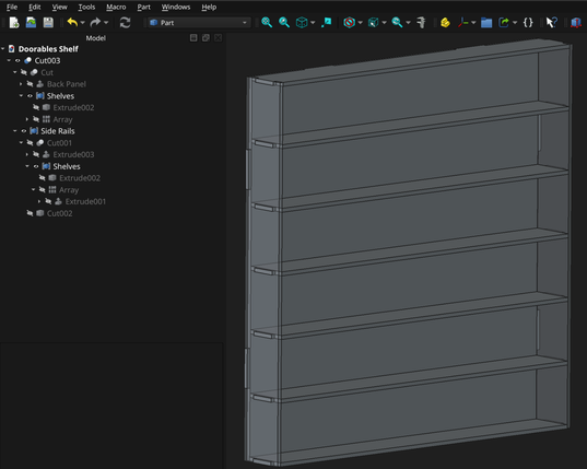
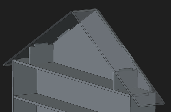
My instincts say that booleans and relying on kerf compensation is going to be the most straight forward way to get good fits, but this little shelf my kids asked for has a seriously complex tree.

I haven't seen any best practices out there. Anyone have any tips or pointers? Anyone else laser cutting with #FreeCAD?

#FreeCADFriday

Started work on adding a roof to the "house" structure and am frustrated that I can't figure out an elegant way to handle the projections to cut a 2d hole in the roof.

Time to call it for the night.

@amd in Solidworks I'd design it as a multibody part and use the same sketch for each matching set of tabs and slots. The laser cutter kerf is plenty of clearance (if not too much of a gap for solvent welding!)

But in FreeCAD with only single-body Parts allowed it's more awkward. I think I'd try having a single PartDesign Part with a bunch of sketches to position all the individual parts, tabs and slots and then reference those in the individual Parts? But I don't know if that works!

@gbrnt I know I can drive the kerf inside or outside the actual cut path in my laser software so I should be able to kerf comp my way to a good fit without having to design overlap into the model.

FreeCAD can do multi body designs in part design now (recent addition) but I’m not sure how I would structure my sketches any better in the part design work bench. Than here in the part work bench. I probably just need to try it and see if something clicks.

My concept was to rely on Boolean cuts so I could only have a 3 sketch model and I couldn’t run into a lot of topological problems from relying on external geometry

@amd Use the same sketch for the pad and via a ssb for the pocket, applying the tolerance in the ssb.

(Not commenting on how much tolerance you need, the other reply about the laser kerf handling that for you may be accurate. I have no laser experience)

@amd Sub Shape Binder.

1.1 will create them in a hidden way when you try to pad a region of a scketch, and you can manually make them with the button next to the sheep (clone) in part design work bench

@amd and they are editable, select extra edges from the sketch then drag the sketch into the SSB yo add those edges. Hold Ctrl while doing that drag and it will replace the edges.

I've been doing some master sketch based designs recently, it is an interesting and powerful design method in #FreeCAD

@LovesTha oh. Sure. Thanks.