I gave mechanisms in the Assembly workbench another try in the newly released #FreeCAD v1.1 but sadly it still completely breaks all the joints when you try to move a part in a mechanism like this. Am I missing a trick here?
@drfootleg I created a new model using some arbitrary dimensions for the linkage lengths. I then put it together in the Assembly workbench using just revolute joints. My assembly doesn’t break?
@drfootleg However, if you drag a component too far, it can “break”. This is simply due to the possibility of multiple geometric solutions. How is FreeCAD supposed to know which one you want? This also happens in SolidWorks. One way to overcome it is to limit how far a given revolute joint can go. This reduces the possibility of the solver jumping between the multiple solutions.
@chrishuck I had a mixture of cylindrical and revolute joints. I've tried converting them all to revolute but as soon as I add the fixed constraint to the main triangle part everything snaps out of the plane the parts are in. Here is my file if you want to have a play:
https://www.transfernow.net/dl/20260330tmBjyPLi
"FreeCAD Carpentoid Assembly" (Carpentoid test v1.1.FCStd) is available for download

Click to download the transfer "FreeCAD Carpentoid Assembly" (1 files, 124 KB) with TransferNow

TransferNow
@chrishuck Also all the joint constraint markers have moved a long way from the assembly, so when I snap to view all, the assembly is tiny on screen as the joint markers are miles away. I don't know how that happened. For comparison, this mechanism behaves very well in Solidworks which I also use. But I would really like to be able to share my project in #FreeCAD if I can get it to work.

@drfootleg I will take a look at your file and see if I can determine what is going wrong. The videos I showed were done in v1.1. I don’t know if that has anything to do with it, but I’ll let you know what I find out. It will be later today at the earliest.

I’m a SolidWorks user in my day job, and sometimes the Assembly workbench workflow in FreeCAD throws me because of decades of doing things a certain way…

@chrishuck My CAD is all hobby self taught, so I'm always learning new tricks. For example I had never looked into restricting the range of rotation of joints in either CAD program, but will now you mentioned it. My latest test was in FreeCAD v1.1 on Windows. I open the file I sent, select the assembly object in the tree, select the triangle and add the fixed constraint to it and things immediately twist out of plane.
@drfootleg I think there must be some conflicts of assembly constraints that are causing it. Sometimes it is because the assembly is over-constrained, much like the warnings in sketches. The solver doesn’t know what to do, and it can be frustrating. At least SolidWorks will tell you if a constraint can’t be solved before you apply it. Or, it will give you the option to apply it anyway an “break” the assembly.
@drfootleg @chrishuck
Hi I've just started to have a look at your file, the first thing that jumps out is this placement. 12.94 metres on x and -11.5 on z
@BertSgroggins @chrishuck Maybe one of the assembly glitches place it 12m away and then the constraints move it back into place in the assembly? I would have designed all my parts at the origin, but I had a lot of trouble with this assembly in v1.0 when I first tried to build it.

@drfootleg @BertSgroggins I tried changing things in your original file, and it exhibited very odd behavior when applying the different joints. I couldn’t quite figure out why.

So, I created a new assembly file, and I inserted the part objects from your original file. I didn’t have any issues applying the joints, and I was able to drive the input link.

I’m going to have to play with your original file more to figure out what’s going on.

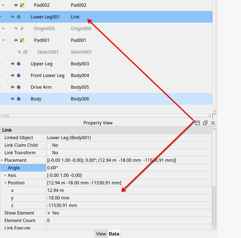
@drfootleg @BertSgroggins So, to Bert’s point, I also noticed the X and Z placement values for each part were very far from the origin, but the Y value seemed reasonable given the thickness of the parts. I adjusted the X and Z values to zero for each part, and tried to apply joints. None of them worked (or appeared WAY out of view). Also, dragging parts around didn’t seem to behave properly.

At that point, I deleted the assembly object, and when it prompted me for whether I wanted to also delete the parts, I said no. This allowed me to create a new assembly object and drag the parts into it. I was then able to apply joints successfully as normal and drag parts around normally. There must have been something corrupted about the original assembly object.

I will also add that it is sometimes helpful to use temporary grounded joints on multiple objects as you add joints. This helps keep things from flying around. You can still use the Transform tool to move objects that are grounded. This allows you to move them closer to other parts to help the joints succeed. Then, just delete the unnecessary grounded joint(s) when you want the ability to free drag for motion. You still need at least one grounded part!

I hope that helps!

@chrishuck Interesting. I have the upper green triangle fixed in place and then the arm attached to the RH side of it is a crank which needs to do full rotations.

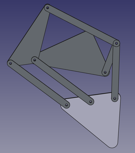
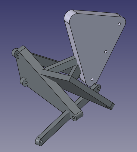
@drfootleg So, like this, then?

(Seems like a Strandbeest?)

@chrishuck Yes, it is actually the Carpentoid mechanism (similar to Strandbeest but with a flatter walking gait). That is really reassuring to see FreeCAD working with a mechanism like this. I will try to diagnose why my assembly built in v1.0 misbehaves so badly.

@chrishuck @drfootleg

That is very cool!

I have not used Assembly and would seriously enjoy a video watching how you put this together. In general I don’t find videos useful but for tools like FreeCAD I find them very helpful.