i have been using it and it’s been fine

but it buzzes now

and also cuts out if you draw more than low power

note

THIS IS NOT THE POWER SUPPLY I FIXED BEFORE it’s different

anyway it’s rated for 10A but is dying being asked for intermittent 6.5

and nothing is obviously hot

so yeah

what’s it likely to be? power transistors?

#PowerSupply #Zzt #repair

@moira The buzzing is probably coil whine in the transformer, from some subharmonic of the switching frequency that happens to be in the audible range.

It's possible there's a bad capacitor somewhere, like in the feedback for the controller, or if the power transistors have a snubber circuit.

@toroidalcore it seemed too low pitch for transformer whine but I didn't think about lower harmonics so maybe that's it

capacitors are easy to check, at least. ^_^

(this is not the same model as the one with the splody cap and the values are all different so ... sure hope I have some lol)

thanks ^_^

@moira You can get weird effects if something goes a little bit unstable, or unstable during certain load conditions. It's kind of hard to say without poking around with a meter or scope.

Good luck!

@toroidalcore @moira if it sounds more like buzzing, it could be the core laminations becoming, er, de-laminated. try squeezing the core (in the direction that squeezes the laminations together) and see if that helps at all.

admittedly this is more common with older, larger transformers.

@wohali @toroidalcore oh it's buzzy for sure

i'm kind of afraid of operating it with the case off given the previous [POW] incident tho'

@moira

Do you have access to an oscilloscope by any chance? I'd be curious what the output looks like when it's doing that.

@wohali

@toroidalcore @wohali well guess what's not making the noise and not cutting out anymore

so it must be heat dependant and there must've been some heat even tho' i didn't feel any

@toroidalcore @wohali WHELP we're back

big voltage drop and the buzz, gimmie a sec for recording

@toroidalcore @wohali and it's leaking 60hz (at very low AC voltage) at all times, I didn't check that before

also I thought the buzz was higher pitched than I'm hearing now but I could be just remembering that wrong

@moira

Is that AC-coupled? That looks like the AC component on top of the DC output. What DC output voltage are you expecting from it?
@wohali

@toroidalcore @wohali It is an AC component on top of DC. I'm expecting 12V, I'm also getting some millivolts of AC leakage at 60Hz, which is the cycle of our AC power.

@moira

Is that image while the supply is running with no load, or is that when it's cutting out? What does it look like as you add load?

Can you zoom in on say the top of that 60 Hz component in that waveform?

@wohali

@toroidalcore @wohali It's the same either way, so this part is a consistent problem. I ... hm, can I zoom in on that? _Sorta_. Lemmie try things.

(it's a very silly little oscilloscope. I should get a better one.)

@moira @toroidalcore that's not terrible AC overlay, but it could be improved with better output filtering.

i assume you're not getting the voltage you expect here? or is it just a buzzing?

as always with these things, suspect the electrolytic capacitors. look for any leakage or funny smell.

here's a very good intro video to how SMPS work if you need one: https://www.youtube.com/watch?v=3FyXqNcqvRM

Every Component of a Switch Mode Power Supply Explained

YouTube

@wohali @toroidalcore oh now when it buzzes it's dropping voltage like a mofo

and quick, too

this is all new, none of this was happening until this afternoon so something yearns to fuck off into the sea

@moira @wohali I second the electrolytic caps having a good chance of being the culprit, but if possible it would be interesting to look at the switching signal to the transistor, and maybe the feedback.

I have to go to sleep, but will check in in the morning.

@toroidalcore @moira yeah, you could try checking the voltage at pin 6 on the IC, but since this can sink/source up to 1A of current through the totem pole config inside the IC you may not see as much as you'd like. be sure you are running on battery power for that oscope of course if you do this! we like an alive moira.

@wohali @toroidalcore oo, someone wants me _alive_ this time, that _is_ new

xD

the tiny scope is hilarious and only battery so we are 1000% safe there

this hasn't been running not, it's been running quite cool which is why the big surprise. it also only has a couple of weeks of use on it, tho' many hours a day during those weeks.

the 6.5A draw is barely more than momentary, most of the time it's drawing .21A according to my bench supply.

The big cap says "nichicon" but I'm rolling to disbelieve. the rest seem to be nonames

@moira @toroidalcore there's not a lot going on in this design.

always suspect the electrolytic caps first. especially if this has been running hot somewhere, they'll be the first component likely to fail - and are often the first component cheaped out on by inexpensive contract manufacturers (China and elsewhere).

if you have a cap tester i'd pull each of the electrolytic caps and run them through it. be sure to discharge them first! you can probably skip C1 for now unless it smells or shows obvious signs of failure.

@wohali @toroidalcore the two little caps near single IC (very similar, separated by resistors) are showing weirdly high ESR in-circuit so that's fishy

the "nichicon" C1 is showing less than half its rated capacity in circuit which is also kinda sus

(I have a dedicated ESR meter, PEAK Atlas ESR70 Plus, sometimes you can get hints from in-circuit components with it)

@moira @toroidalcore ah, ok, i don't expect everyone to have an ESR meter, esp. not an in-circuit one.

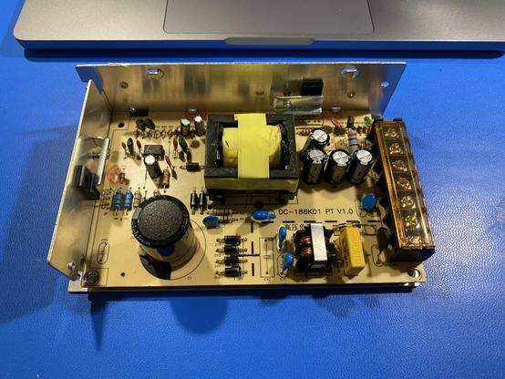
the caps near the meter there are may not be as critical, esp. if they are just decoupling for Vcc on pin 7. (the 8-pin package won't have pins 11 and 12 broken out, they'll be connected internally.)

C1 is going to be the post-rectifier filter on the input side and, while it'd be interesting to look at, is probably something you're not setup to probe with your current gear?

you could check that the IC is at least getting the power it expects at pin 7 safely, if that's all over the place the controller isn't going to be doing the right thing at all.

@moira @toroidalcore i'm off to bed... good luck with your probing! stay safe.
@moira @toroidalcore oh, one last thing, i don't always trust in-circuit measurements, even with the ESR70. If you feel confident lifting a leg, that will give you a result you can be more confident about.

@wohali @toroidalcore the esr is one of the relatively few fancy tools I have

both it and my true RMS multimeter say this 150uF cap is more like 70uF so that seems kinda bad

@wohali @toroidalcore also i've done things like make my own effects boxes and microphone preamplifiers and repaired board level faults on computers so while sure I'm a bit of a duffer I'm not completely unfamiliar with electronics

@moira @toroidalcore i do my best not to assume anything! but i also do my best not to talk down. it's clear you are not clueless!

i only mention the leg-lifting because it's my standard practice. with in-circuit ESR you need to have some confidence you know the inductance of the rest of the circuit from the capacitor's POV, that it is not paralleld with anything else that will induce a reluctance, that the 20mA or so it injects for larger caps isn't going to do weird things, and understand that e.g. in the ESR70+'s case it measures at 100kHz, which is not at all the frequency value that matters for C1 (that'd be 60Hz). i believe the newer ESR70 "Gold" measures at 50kHz, and devices like the DE5000 (and other LCR meters) have selectable frequencies.

hope the brain dump was enjoyable, now back to cookies 🍪

@wohali @toroidalcore I like you already so I'm not mad it's okay xD

There are two others of these sitting around old-stock-in-box (all 2020, yes these were get-what-you-can-get plague purchases lol) so I grabbed another to make comparisons and in circuit and the equivalent cap on the working one actually measures as labelled even still on the board. So this one is clearly a nonsense boi

tho' this does beg the question of "how did this work for a while?"

still want to fix it tho', if I can

@moira @wohali Another thought is the voltage rating on the caps. If the one that isn't working doesn't have enough derating those caps won't last as long, so they could be deteriorating.

@toroidalcore @wohali Possibly - they're still testing basically the same across both units tho'.

I also checked all the diodes while I was in there and they're testing fine in-circuit except for D8 which I can't actually test because it's in parallel with a resistor so probably a noise-reducer I think? But it looks okay for whatever that's worth

@moira @toroidalcore might be part of the snubber

@wohali @toroidalcore I have not yet watched the video so I do not yet know what that is xD

one of the power transistor's just off to the left if that means anything

@wohali @moira Keep in mind that C1, or the bulk capacitor, also helps supply the slug of current whenever the power switch turns on. So it is interesting to see how the cap performs close to whatever the switching frequency is.
@toroidalcore @moira Fair enough, the switching freq is probably closer to the ESR70's testing freq.
@toroidalcore @wohali I don't have any ability to test that, unfortunately, so I just have to go off my ESR70's base reading. But what's important is that it does not match how another (working in quick/light testing, actually gonna make sure later) unit's C1 tests.
@moira @wohali Definitely a good indication something is not-quite-right.

@wohali @toroidalcore also this "nichicon" weights absolutely nothing

i wonder if there's literally a smaller capacitor inside this bigger one xD

@moira @toroidalcore entirely possible. looking at the Vcc voltage on the IC will tell you if it's doing its job well, and is safer than directly measuring the primary winding voltage on that transformer.