I am doing some #sociology, #ethnomethodology and #electronics work - trying to breadboard an oscillator that will eventually go in a multi-oscillator audio device - and I have RUN AGROUND. So partly the thread that follows is me rubberducking stuff, partly it's me doing 'fieldnotes' (of the 'normal troubles' of following schematics) and partly it is a desperate cry for help from anyone who might be able to offer it.
SO, I'm trying to build an audio device - a drone machine that uses very simple oscillators without the usual 555 timer chip. Instead, it uses a principle called "reverse avalanche" which is a kind of mode of using a transistor where you cut off the middle of the three pins (the base pin?) and sending enough voltage through it causes it to oscillate and produce a sawtooth wave. Just six components per oscillator, and I want to put 5 or so in a single box, using different capacitors...
...to change the pitch range of each oscillator. Each oscillator is tunable in a rough way with a potentiometer, so the idea is to get these kind of polyphonic drones type of thing going on. This is not my idea, but comes from LOOK MUM NO COMPUTER (https://www.lookmumnocomputer.com/simplest-oscillator), who has incidentally just been announced as the UK's entry for Eurovision 2026.

So I've been trying to breadboard a single oscillator out, so I can get a handle on how I could translate this to perfboard, so I can then make a few, join all the power and outputs together, and they'll (hopefully) work as a single device. The trouble is, I haven't been able to get it to work at all, so I wanted to put my efforts down in a thread to work towards figuring out (hopefully with help from others!) where I'm going wrong - I have some ideas of where things MAY be going wrong...
...but which of those ideas is right? And what would I need to do to fix whichever it ends up being? That's where I'm aground here.
First thing though, I've got some parts and I've already familiarised myself with how to use a breadboard - see?? An LED is lit! Which means the breadboard is functional, the LED works, the resistor (1k) isn't broken, the battery has charge, etc.

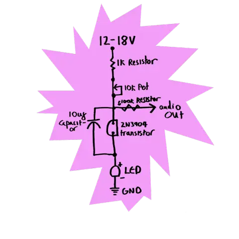
The task from there has been to translate the below schematic to the breadboard. I assembled a collection of parts. But crucially, across the LMNC resources, the schematic doesn't quite fit what he ended up making - the transistor used in the schematic requires 12-18V power to oscillate, but he also went on to say using a different transistor (an SS9018) you can oscillate this with a more standard 9V supply. So I got some S/SS9018 transistors and went with that.

But I noticed that LMNC also provides a stripboard layout, which visualises things (for me at least) a bit more intuitively. Or rather, there are MULTIPLE stripboard layouts, which don't always seem to show the same thing...so immediately I'm in a place of not knowing HOW to put the schematic onto the breadboard. Three different versions below - note where R2 is, the orientation of the capacitor, the addition of CV controls (can I just ignore them? I think so, but don't know for sure), etc.


I've tried following a few of these, but none of them have done anything at all - no audio output, no LED lighting up, nothing. So, maybe I'm just building the circuit wrong on the board? There's an element of translation going on here, in that the stripboard layouts don't QUITE work the same as a breadboard, where I've been using power rails to free up board space (and to create a ground network rather than soldering wires together at this stage), and having to use jumper wires to connect...
...the two halves of the board. So see below for my efforts here - I'm not sure how useful this pic is as the jumper wires create a lot of visual mess, but as far as I can see this follows the principles of which pins connect to which others as shown in the stripboard layouts - PLEASE let me know if I've just made an error though! Circuit closeup included.


My translation efforts may be the cause, as I've read comments on the videos etc so I know SOME people have got this going, and even those with problems getting the audio out have had a working LED (whereas I have not) so user error? In which case, where's the error, and how do I fix it?
But there are some OTHER potential problems too, and it's not being able to identify WHICH might be the culprit that's throwing me off here too.
Firstly, are my transistors right for this circuit? I bought some S/SS9018 transistors on the basis that these were discussed by LMNC as being able to oscillate at 8V. But they're harder to find, and the ones I got off eBay are S9018 rather than SS9018. Anywhere I've looked on t'interweb suggests that they are basically interchangeable, but are they interchangeable in THIS PARTICULAR CONTEXT (which is a weird one since you're using the transistors in this reverse avalanche mode, and...
...cutting the middle pin off. So I may just have transistors that won't do the job I need them to do?). I've looked at datasheets for both, but I'm newish to this so it's hard to know what to look for.
Another potential issue...am I doing something wrong with the output? Am I setting up a ground network correctly (which if I haven't might account for why I may not have a completed circuit which can't power the LED)? I'm trying to put this into a 1/4inch jack so I can send the signal to an amplifier - does that work and have I done this right, or does it need to go directly in to a speaker for some reason I haven't anticipated?
Does the type of cable I'm using to connect the output jack to the amp matter, in the sense that there are differences between cables (TRS, etc)?
Do the other components need to change as I'm changing the transistor (eg different resistor values? Different potentiometer?)?
I'm not sure which of these options applies here, and it would be great if anyone could help at all, as I could do with getting this device built pretty soonish (I have some plans to use this device in some ongoing research on improvisational practice in music), so any help much appreciated! But also, I'm keen to kind of put this whole process down somewhere as an ethnomethodological thing as there's potentially interesting/relevant stuff to note here I think.
Basically, anywhere I've tried to look for learning resources about turning schematics into breadboard is quite noddy - "there's your schematic, easy right?". But as soon as I start putting components on a board, I'm thinking about which way round to connect the power (electrons flow from negative to positive right? I don't want to blow up a capacitor, nerves!); how to read bands on a resistor (they're not polarised sure, but the bands themselves are not symmetrical so it matters which way...
...round you hold the resistor as you're trying to identify it matters); my breadboard doesn't have as much space as the stripboard layout - does it matter that I've placed components "closer" together (I don't think so, as long as the right pins are connected to each other in the right way, but then what do I know?)?; can you use a negative power rail as a ground network?; yada yada yada yada...
These kinds of practical concerns are really difficult to relate to learning resources as they're typically laid out, it's in the DOING that you encounter and deal with these troubles. But as I'm doing this by myself, I only have my own eyes and inexpert knowledge to rely on. Which makes it hard to disentangle what the actual issues might be, and hard for me to "see differently" and "think differently" as to what to do. I've had various goes at this across different non-consecutive days...
...(fresh eyes), and rubberducking still relies on ME having an answer to a problem (it's more about clarifying the problem and the answer is supposed to follow...but where I go, there I am; maybe if I don't have an answer, clarifying the problem doesn't help me much?).
And that's where I think I will unsatisfactorily leave this thread - like I say, ANY help on ANY of the above much appreciated, whether that's ideas of how to tweak the circuit as I've built it, or just thoughts and comments...
...on the stuff I've been thinking about as part of all this. Thanks for following so far! 🙂
...AND ANOTHER THING. Visual mess. Schematics are clean and simple (barring the troubles noted above). But circuits are not. Hard to diagnose. Hard to follow where power is going. That feels like a thing too - I've been trying to sequentially organise how I build the breadboard version (which parts are placed first) with that complexity in mind, and also in respect to the tactility of things (eg its quite hard to place these components in at times, fiddly).
@pdbrooker the photo of the breadboard is (as you noted) a bit tricky to follow to check.
If you haven't cracked it by Thursday you should bring it to #MakerNight at @DoESLiverpool
We'd be able to check your circuit pretty easily in person, and the bench power supply would let you try 12V (or more) to it to see if that's the issue; and we've got a 'scope if you need to get really into the weeds with it.
@amcewen @DoESLiverpool Amazing, thank you! Would be great to finally get along to DoES in person more than anything :-) But yeah, even thinking of the sociology side of things, there's plenty written about the need for social networks to get things up and running, all seems pretty relevant today!
@pdbrooker yeah, totally! The tricky bit might be that you'll get /too many/ opinions on how to fix things 🤣
Once you've got it working then you'd need to come to @DoESLiverpool again for the Liverpool Synth Meetup 😁