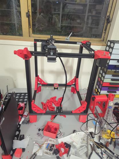
Recently, I got my hands on a free Ender 5 Pro, whose Z axis was so bent it looked like a forklift drove over it. Because of that, I can finally do an #Endorphin build!

This thread will be an extended sojourn into this project, where I will aim to use random workshop junk whenever possible. I won't make this a hard rule, but I'll try and avoid buying new if I can.

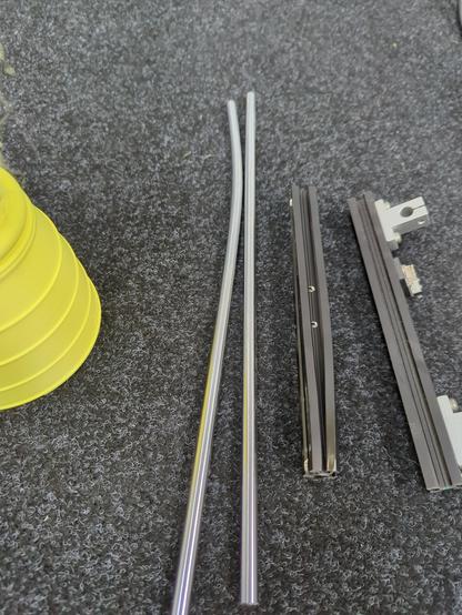
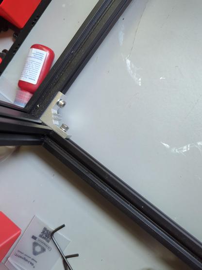
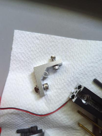
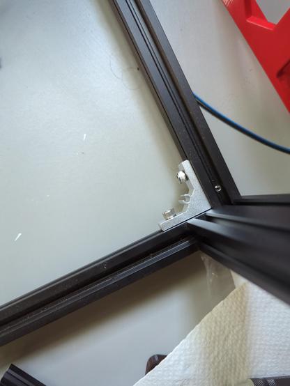
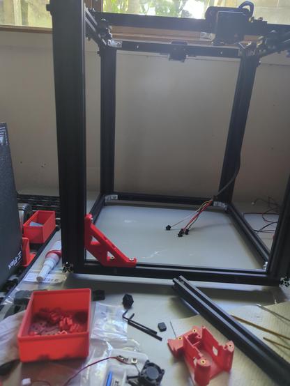
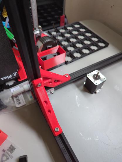
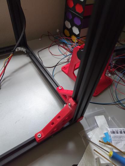
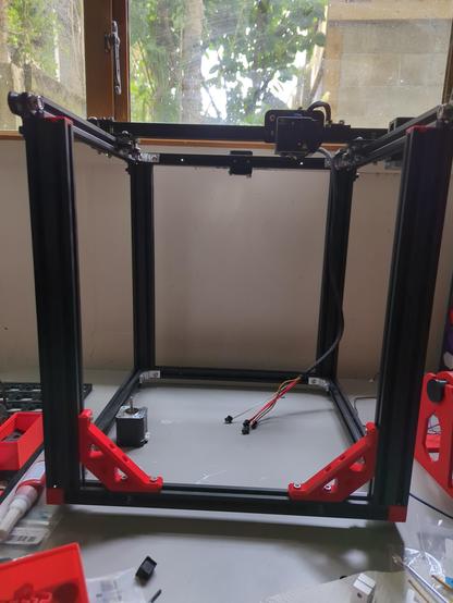
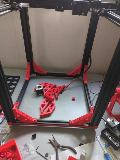
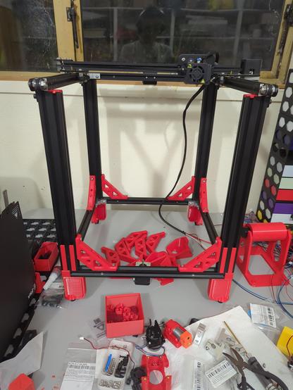
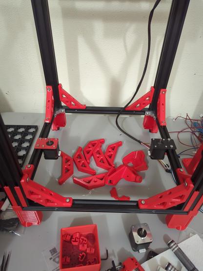
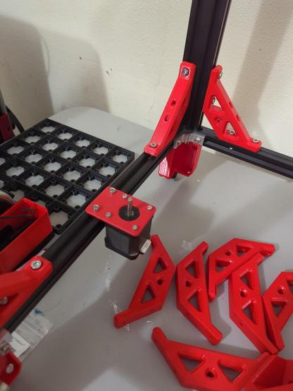
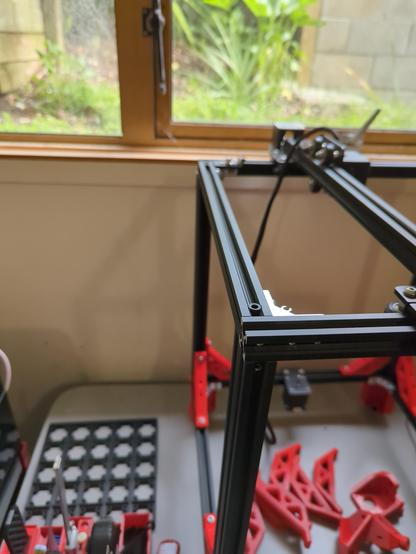
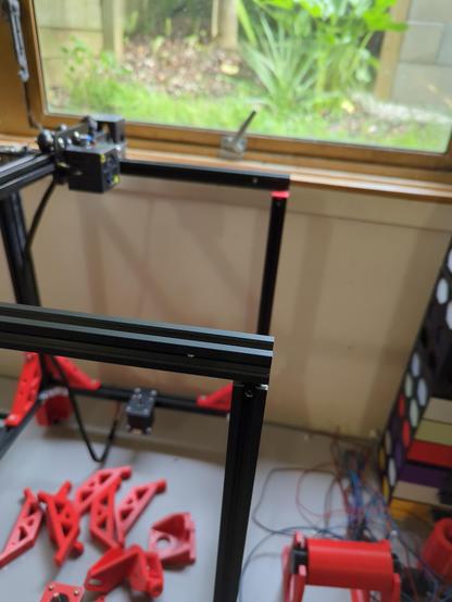
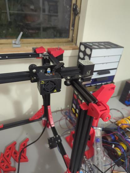
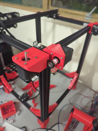
First things first, gotta strip down the frame! So much useless junk there.

@3dprinting #3DPrinting #FDM #DIY

1/n

@3dprinting I wasn't kidding when I mentioned that forklift. _This_ was the state of the Z axis when I received this printer.

2/n

@3dprinting One of the first things I did was repurpose the metal reinforcing brackets that used to support that crossbeam into supporting the bottom where the electronics housing used to be. These needed two M5x12s and two M5 hammer nuts each. I couldn't reuse their existing M5s, as they were designed to go into tapped holes in the frame and were thus too long.

3/n

@3dprinting Oh, almost forgot. Anyone who's interested in what an Endorphin is can check out the project page here: https://endorphin3d.com/docs

The tl;dr of the Endorphin is that it's a minimal set of Ender 5 upgrades designed to fix many of its issues, by making use of an unusual choice of kinematics (hybrid CoreXY). Unlike something like a Mercury One, which is a near-total rebuild, this is a small set of upgrades.

4/n

Introduction

The Ender 5 as it should be

Endorphin 3D

@3dprinting I won't limit myself to the Endorphin's upgrades though: at minimum, I will have to rebuild the entire Z axis, and I'll have to do plenty more besides. However, I always liked the Endorphin for how small and simple it was, and thus, decided it would be a workable project that can use up a bunch of workshop junk.

5/n

@3dprinting One of the first _printed_ upgrades will be some brackets to reinforce the frame. I found one that I liked here: https://www.printables.com/model/82832-90-degree-bracket-for-2020-extrusion-for-ender-5-p

However, the intended print orientation is somewhat suboptimal (thanks, Slant3D!), so I modified it a bit to add a sacrificial layer, which allows it to be printed in a more optimal way. I'll need quite a few of these: I'll start with the ones reinforcing the two Z columns at the front.

6/n

@3dprinting For material, I'm sticking with my 're-use' theme and using KiwiFil rPETG, which comes from 100% recycled feedstock. It helps that I have about 1.5kg of it lying around too. As I have no plans to enclose this printer, this will work fine, and will look amazing, as it's Race Car Red.

For those interested, this is the filament: https://www.kiwifil.shop/products/race-car-red-rpetg-100-recycled-1-75mm-1kg

I _will_ make an exception for the toolhead fan duct, which will be made of ASA, but that's a future Koz problem.

7/n

Race Car Red rPETG, 100% Recycled, 1.75mm, 1kg

@3dprinting I'll also need to find some way of covering various bare extrusion ends (four in total) that are left by removing the top-front crossbeam and the original screen mount. I'm thinking of using these: https://www.printables.com/model/642540-2020-end-cap-with-chamfer

If anyone can suggest a better one, I'm all ears (eyes?).

8/n

2020 End Cap With Chamfer by Travis | Download free STL model | Printables.com

Printables.com

@3dprinting One more-than-mildly annoying problem with the Ender 5 (in any variant) is that two of its motors are not really reusable. The original E motor has a round shaft with a weird press-fit gear on it, which makes it hard to use for anything. Additionally, its weird dual-shaft Y motor isn't too great for anything either. The X and Z at least can be re-used (and match AFAICT).

Not a huge issue for me though, I have two LDO Speedys gathering dust.

9/n

@3dprinting Stage 1 of the Endorphin needs some idlers of a type I don't have, so unfortunately I had to order some. Luckily, Powge had them, and they weren't expensive. Still waiting for them to arrive though.

10/n

@3dprinting One down, _many_ to go. I'll publish the design as a remix of the original. This also shows how vibrant the Race Car Red PETG looks next to the black extrusions.

11/n

Ender 5 4-bolt corner bracket, Slant3D optimized by koz | Download free STL model | Printables.com

Printables.com

@3dprinting So, time for some absurdism. Remember that destroyed Z axis I posted pics of earlier? Seems like the Z motor was also a victim: the shaft is _so_ bent it has _visible_ runout.

However, not all is lost! I thought I had two LDO Speedys in my workshop junk pile, but it turns out I actually have _four_.

Yes, I am going to run _Speedys_ on my _Z axis_. Like an absolute maniac.

13/n

@3dprinting A little bit later, progress! Unfortunately, I ran out of the M5x10 bolts I need to make more brackets, but even these four make the frame _feel_ stiffer.

I also printed some covers for the extrusion ends exposed by some of the stuff I removed, which looks much better.

Next step would be using some 2020 extrusion covers to hide the rather ugly holes drilled in the extrusion in several places. Going to try these: https://www.printables.com/model/208845-2020-aluminum-extrusion-cover

14/n

@3dprinting Predictably, that design didn't work out. However, I found a design that I could remix, and now, the ugly holes can be covered!

I under-printed by about 6mm, so I'll probably just fix that up later.

The design I worked from is here: https://www.printables.com/model/1169141-slot-cover-for-2020-extrusion . I'll post my remix later.

15/n

@3dprinting Pictured: an absolutely normal amount of reinforcement for a frame. For reference, together with the four already printed and installed brackets, this adds over _half a kilogram_ of weight to the frame. PETG be thicc like that.

And yes, that is one of the Speedys going into the Z axis.

16/n

@3dprinting The reinforcement shall continue until morale improves.

17/n

@3dprinting This is the plate for the Endorphin Stage 1. All but one of these parts ended up needing tweaks by me, mostly to add chamfers, remove captive nuts in favour of heatset inserts, and in the case of the idler mount, to fix some _serious_ weakness issues.

I also managed to find bugs in _both_ the AMF _and_ STEP exporters in #FreeCAD in the process. I truly am a bug magnet.

18/n

@3dprinting More positively, I think I've decided to go for the EVA3 as my toolhead. However, since the _only_ hotends I have as workshop junk are E3D V6s, finding a hotend mount was a bit of a challenge. However, this one here works great: https://www.printables.com/model/201093-eva-30-e3dv6-revo-revo-micro-hotends-mount . The fact the groove mount is still free to rotate is not ideal, but I don't really know of a good solution for that anyway.

19/n

@3dprinting "But Koz, won't this have absolutely garbage flow?". Normally, dear reader, you'd be right: however, through the magic of the ZS Plus nozzle collection I've acquired, this should be far less of an issue.

20/n

@3dprinting The upcycling continues! For the extruder on the Endorphin, I was originally planning to use a NEMA17 pancake I've had lying around for ages. However, I quickly found absolutely _zero_ extruder designs fitting that. So I did some more digging, and found:

* A TL all-metal K1 Max extruder replacement: https://trianglelab.net/products/k1-series-extruder ; and
* This 0.9 degree NEMA14 pancake: https://www.omc-stepperonline.com/round-nema-14-bipolar-0-9deg-9-ncm-12-75-oz-in-1-0a-%CF%8636x17-5mm-4-wires-14hr07-1004vrn

They fit together like it was meant to be.

21/n

@3dprinting "But Koz, how on $DEITY's green earth are you going to mount that to the EVA you're going to use?"

Good question, dear reader. However, I am in luck. This is meant to be a drop-in replacement for the K1 extruder, and some kind soul has done the work already: https://www.printables.com/model/770682-k1-extruder-for-eva-3

Now, the existence of this model implies someone wanted to put a K1 extruder on an EVA. This is tantamount to fuelling your racecar with moonshine, but I won't look a gift horse in the mouth.

22/n

k1 extruder for eva 3 by spillo's word | Download free STL model | Printables.com

Printables.com

@3dprinting Is this what everyone posts on OnlyFans these days? đŸ˜¹

More seriously, I modified these from the Mercury One's feet. The changes were to use M3 instead of M5 fasteners to the frame, and replace the captive M5 nut with an M4 heatset so I could upcycle the feet from the Ender 5. Looks really fantastic, and adds yet more frame mass. Needed two M3x10s, plus one M4x12, together with two M3 hammer nuts.

23/n

@3dprinting With that, I can also install the Speedys that will run the Z axis. The brackets are of mismatched colours, but that's just how they came, and I'm not going to let metal motor brackets go to waste.

24/n

@3dprinting So, slight rethink. I decided that I'd rather use the Z axis Speedys on the Y with this dual-Y mod: https://www.printables.com/model/520947-ender-5-plus-dual-y-axis-motor-mount/files . In the process, I discovered that the _only_ way to tension the Y belts on the Ender 5 involves _throwing your frame out of square_. Yes really. You have to remove a _structural_ component to _tension the belts_. Wtf Creality.

So yeah, more frame stripdown!

25/n

@3dprinting In the meantime, I've been making progress on the EVA3 I'm going to use. The next step is to make mounts for the dual 5015 fans for part cooling, and also the duct, which will _likely_ be the Tri-Horn. The duct will be made of ASA, as PETG isn't really up to that task. I also need to mount a Biqu Microprobe I have lying around, which will involve both a BLTouch mount _and_ an adapter, because the jank will never cease.

26/n

@3dprinting Today has been a day of... interesting progress. The dual-Y mod is mounted, but is currently quite loose, as I cannot attach it from the top and bottom. The reason? The same M5x10s I need to finish reinforcing the frame.

I think this is _the_ first time I've had a build bottlenecked by _fasteners_. It's kind of absurd. More are on order, but Aliexpress takes a hot minute.

As an aside, this build is starting to look like something Ivan Miranda would make.

27/n

@3dprinting I'm kind of freestyling here, as I don't (yet) have the idlers I need to do the mod properly. I also have to re-belt the Y, but that can wait until I can do the proper Stage 1 work.

One 'fun' discovery is that the Y assembly is weirdly structural on the Ender 5. This is most notable when looking closely at the dual Y. That bearing there is supporting _nothing_, but I can't remove that part, because it ensures the corner doesn't come off the pillar!

28/n

@3dprinting The eagle-eyed among you might have noticed that the Speedys are gone from the Z axis. This is indeed what has happened, as the dual-Y mod is _definitely_ a better use of Speedys. I managed to find some random garbage motors I could use there instead. Their shaft lengths aren't _quite_ the same, which I suspect _will_ come to bite me later, but that's a problem for future Koz to worry about.

29/n

@3dprinting The wise among you might be scratching your heads right now. "How the hell is he planning to run dual Y _and_ dual Z off a Cheetah?"

Yes, that could be a problem for sure. However, I already figured out a solution to this, in probably _the_ stupidest way possible. I'll explain that next post.

Meanwhile, let's skip even _more_ steps and print the mirrored Y tensioner from Stage 2. Otherwise, I have a _very_ loose corner, and it bothers me.

30/n

@3dprinting To explain how on earth I plan to run 6 motors, we need to consider power. The Ender 5 comes with a single LRS-350-24, which is _definitely_ going to fall short with all my upgrades. I _do_ have an HS-250-24 lying around, which would give me the power I need, but the Cheetah only has one input for power.

The solution? Double up with the original board! I can run one with the LRS, the other with the HS.

Sounds crazy? Yes, but let me explain.

31/n

@3dprinting Given that the heated bed wants 220W, I can drive it from the original board with the HS-250-24. In addition to that, I can drive the E motor from that board, as the poor little 0.9 degree pancake I'm running there is 1A peak, which means something like 0.7A RMS. That's pushing my luck a tad, but _should_ fit into the HS.

32/n

@3dprinting _Everything else_ can come off the Cheetah, run using the LRS-350-24. This gives me four steppers, one of which has two motor connections. That means I have a dedicated driver for _each_ Speedy, and then I can share the garbage Zs.

I am a _touch_ bottlenecked given such mighty motors here. The Cheetah has soldered-on TMC2209s, which have 2A peak current, while the Speedys can tolerate 2.5A peak. This will limit their performance some, but hey, this whole build is jank anyway.

33/n

@3dprinting Now, my original plan was to have a swingout electronics box with a 7 inch touchscreen I had lying around. Obviously with all these boards, this isn't really viable anymore.

However, with those feet, we now have an actual electronics well, which _should_ fit both the PSUs and boards, just. Then, the swingout electronics box can just house the BPi running Klipper and the screen.

Easier wiring, less designing, perfect!

34/n

@3dprinting With that in mind, I need DIN rails, as well as a way to cut them. Luckily, we can crib lengths from the Mercury One project, and I do have a local source for DIN rail.

Guess who is _also_ the proud owner of a new reciprocating saw?

35/n

@koz it’s so you can tell starboard from port
@voided Plus, the colours fit!
@koz like it was meant to be like that from the start
@voided This entire project has felt ordained from the start. From the free-but-in-need-of-saving frame to the fact that I basically had almost everything lying around my workshop, in some cases for _months_.

@koz @3dprinting hey, don't knock the drinkable fuel! The Soviet Union used to have issues with people stealing the MIG-25's fuel* to get drunk off of. Good enough for fighter jets, good enough for race cars!

* ok, sure, it was the jet's coolant, not fuel per se.

@koz when I printed slot covers for the trident I found they scaled along their axis perfectly in the slicer, so I could make them whatever length I needed for each slot.
@amd Yeah, I did exactly that, I just measured badly.