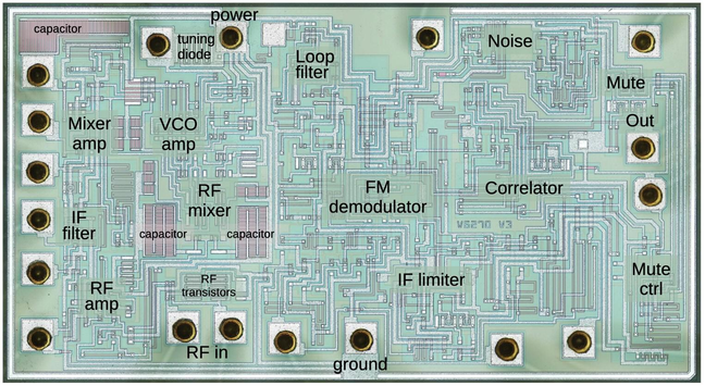
In 1983, Philips produced the first FM radio receiver on a chip, leading to products such as the FM radio wristwatch. Let's look at the tiny silicon die inside this chip and see how it works. 1/N
Here's a die photo of the FM radio chip, the TDA7000. You can see the greenish silicon, with white metal wiring on top. The 18 white squares around the edges are the bond pads that connect the die to the chip's pins, with gold wires attached. I've labeled the main functional blocks of the chip. 2/N
This close-up of the die shows how the metal wiring (white lines) connects the underlying silicon structures (gray and green). Unlike modern chips, this chip only has one layer of metal, so the wiring needs to twist and turn when other wires get in the way.
Transistors are the main components of the chip, amplifying signals and performing other functions. Modern chips use CMOS transistors, but this chip uses NPN and PNP transistors. These diagrams show how the transistors look on the die, along with cross sections showing the silicon layers.
Another important part of the chip is the resistors, which impede the flow of electricity. They are typically long and zig-zagging. The ends of the resistors are connected to the metal wiring. The arrows indicate the holes in the insulating oxide layer where these contacts take place.
The most unusual components in the chip are the "varicap diodes", which help adjust the radio's frequency. These special diodes act as capacitors with a value that can be controlled by changing the voltage.
The chip uses these components to turn an FM radio signal into audio by combining an oscillator, mixers, filters, amplifiers, and other circuits. If you want to know more about this FM radio chip, I go into great detail in my blog post: https://www.righto.com/2025/08/reverse-engineering-analog-TDA7000.html
How to reverse engineer an analog chip: the TDA7000 FM radio receiver

Have you ever wanted to reverse engineer an analog chip from a die photo? Wanted to understand what's inside the "black box" of an integrate...

Credits: Thanks to IEEE for providing the die photo.
Wristwatch photo from a Philips article: https://www.cool386.com/tda7000/technical_review.pdf
Lots more information on the TDA7000 chip here: https://www.cool386.com/tda7000/tda7000.html
Application note with details here: https://www.tel.uva.es/personales/tri/radio_TDA7000.pdf

@kenshirriff

Wow. How long did batteries last on those?

FM radio must require much more power than a typical wristwatch.

@kenshirriff that's one of the best blog posts ive ever read! Thank you for writing and sharing it!

@kenshirriff What's the point of the noise source? Don't you naturally read noise in between channels, is that not sufficient? I'd expect the VCO to be slewing around randomly due to an unlocked control loop.

WRT all the crazy single layer routing chips and exotic BJT layouts, I don't know how you do it. The oldest thing I've done any significant RE on was 350nm CMOS and most of what I've done lately has been 180 to 45.

It's sooo much more readable when everything is standard cells, all your NMOS in a nice row, all your PMOS in a nice row, all of your wiring mostly on orthogonal axes, all of your layers mostly planar, etc. Sure you need a SEM and fancier delayering equipment but once you have the data it's so much easier to make sense of.

@azonenberg From the application note, I think the main issue is if the VCO locks onto a sideband, then you get distorted audio. It's better to replace this with white noise so the user knows that the tuning is off.

@kenshirriff

> Moreover, FM radio provides stereo, while AM radio is mono, but this is due to the implementation of radio stations, not a fundamental characteristic of FM versus AM.

They did try stereo with AM. One method used was Independent Sideband modulation, something like running two SSB stations, the LSB station carrying the left channel and the USB carrying the right … a DSB AM receiver will just get both sidebands mixed together (mono) but a ISB-capable receiver will detect the individual sidebands and receive them separately. This requires very sharp filters which get pricey.

The other way, was Motorola's C-QUAM. Basically it used Quadrature Ampitude Modulation: it relied on the fact that a conventional AM receiver would not detect phase… but using two AM detectors, with reference oscillators with a 90° phase difference, could detect the in-phase (I) amplitude, and the quadrature (Q) amplitude independently.

So I was effectively the mono signal (left + right), and Q contained the differential (left - right). There was some signal processing to the Q signal to ensure it didn't interfere with the I signal.

This was tried here in Australia, but apparently was not that successful, and quickly disappeared once FM stations started appearing in the 1980s (about the time they moved AM stations to a 9kHz separation to make room for stations that would never exist).

https://en.wikipedia.org/wiki/C-QUAM

C-QUAM - Wikipedia

@kenshirriff
Pretty sure this is the grille of a Jeep.