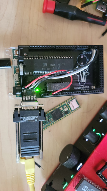
This is my Arduino8088 board. It's a basically a simple passive adapter to connect a 8088-compatible CPU to an Arduino MEGA or DUE.
I used this to create JSON CPU tests for the 8080 and V20 CPUs. You can find those here:
http://github.com/singlestepTests/8088/
http://github.com/singlestepTests/V20
These test suites include 10,000 executions of each opcode, including undefined opcodes, capturing the entire bus state of each instruction.
These can be used to data-mine statistics about instruction execution, flag usage, or verify an emulator's accuracy.
The only reason this works is that the 8086 and the 8087 were designed as full coprocessors. The 8087 maintains an identical copy of the CPU's prefetch instruction queue.
To do so, the CPU must tell the 8087 when it reads from the queue. It has a 2-bit status value for this purpose.
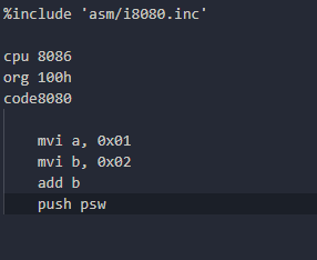
Here's what that looks like.
Here we perform 1 + 2 and then PUSH PSW to capture the result and flags.
If you look carefully at the end you will see the accumulator pushed to the 8080's stack via <- w 03
I found this very convenient import for NASM that allows us to write 8080 code, so I didn't really have to do anything except import it.
I hope to be able to add tests for the V20's 8080 instruction set to my V20 test suite.
It will be a bit awkward as you'll have to analyze the bus states to check the flags, but, maybe I can do a little post-processing magic to extract them for you and add them to the JSON.
I still have some ideas - if the first thing we do after resetting the 286 is set the trap flag, then we should be able to detect execution of the trap handler as our instruction boundary.
This will of course slow things down incredibly, but I'm not sure what other option there is.
But if that method works, we could in theory even do this with a 386. There was a CMOS 386 designed for embedded devices with a 16-bit data bus, the 386 EX.
There are just barely enough pins on an Arduino GIGA to connect everything.
You can find the KiCad files and source code here, if any of this interests you:
I'm going to start adding 8086/V30 support.
The easiest thing to do would be to have a #define for it, but that would require reuploading the sketch every time you wanted to switch CPUs. I don't like that, so I think I should auto-detect what CPU you have.
How do you detect an 8086? Well, the same way the 8087 FPU does.
The 8086 defines one pin differently, Pin 34. This pin becomes !BHE - Byte High Enable. This is an active-low signal that indicates the upper byte of the data bus is active (IE, we are doing a 16-bit transfer).
The 8086 pulls this pin low on reset. The 8088 doesn't.
I'll print the the logical indication of active BHE in my trace log format with a capital B.
Here I swapped out an 8088 with an 8086 and reset the board. You can see the detection is working:
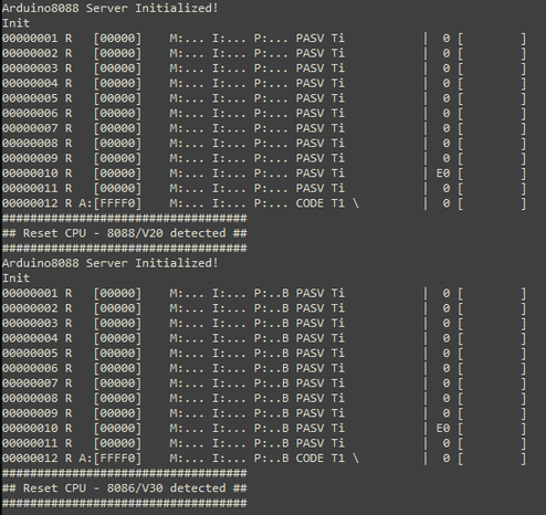
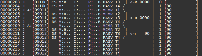
The 8086 only ever fetches 16-bits at time. It can also only do so at even addresses.
So what happens when you jump to an odd address - the CPU needs to fetch from there, doesn't it?
The way the 8086 is designed it can only read 16 bits at once from an even address. So to read the odd-addressed byte, it must read the preceding even-addressed byte as well.
This produces a word containing a dummy byte and the byte at the odd address. The 8086 then throws away the dummy byte, putting the odd byte in the queue.
You might wonder what happens when a 16-bit CPU like the 8086 writes to an 8-bit IO port.
The 16-bit write has to be translated to 8 bits. Surprisingly, this isn't the job of the CPU.
I wrote up how this works here
https://oldbytes.space/@gloriouscow/114225311659566619
Anyway, back to Arduino8088. My protocol has a version command, that typically returns the string 'ard8088' and a one-byte version number.
I could add a new command to get the cpu type, but I could just be lazy and return either 'ard8088' or 'ard8086' , depending on what was detected.
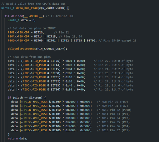
More progress - the state of the BHE pin sets a data_width parameter at T2 , which I use to control formatting.
A capital R indicates a 16-bit read, lowercase r indicates an 8-bit read. Same for writes, except W and w.
We're still only fetching one byte at a time and putting one byte into the queue, that's the next thing to fix.
I've got 16-bit fetches implemented, and hopefully have handling of odd and even address fetching correct.
Here we see a good sign - I inject a JUMP FAR to D000:0000 at the reset vector, because being 16 bytes from the end of memory isn't a lot of room to work in.
We can see D0000 get latched, which means we made it! Now we just have to execute the register load program....
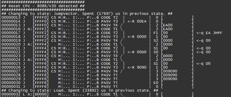
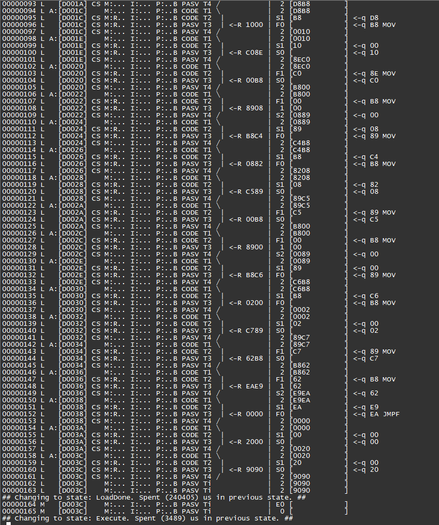
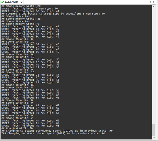
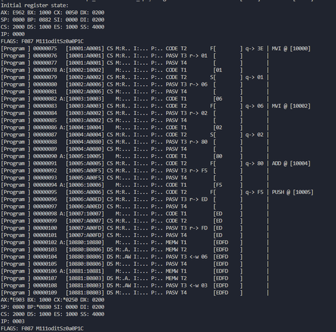
At this point control is handed back over to the client - the client must read the address and status pins, then write to the data bus to feed in whatever programs it wants to run.
Once it is finished, it sends a Finalize command to the Arduino which will then execute the register Store program to capture the final register state.
We could add V20/V30 detection, too. The V20 (and I assume the V30 by extension) has an alias for XLAT at D6, whereas the 8088/8086 has the undocumented opcode SALC.
Just measuring the execution time of D6, in combination with the previously determined bus width, should tell us which CPU we have.
A one byte CPU detection routine, how's that for size coding?