This is my Arduino8088 board. It's a basically a simple passive adapter to connect a 8088-compatible CPU to an Arduino MEGA or DUE.
The Arduino runs a sketch that controls the CPU and implements a simple serial protocol to clock the CPU, read and write the data bus, and report the status of the address and status lines.
The little RS-232 board is optional - it supplies an OOB channel for debugging messages and tracing.
The main serial protocol runs across the USB connection - on the Arduino DUE this runs at native USB speeds, so 480Mb/s, which is decently fast but we still clock the CPU quite slowly. CMOS process CPUs are recommended as a consequence.
I wrote client software that runs on your PC, and can execute a binary on the CPU via this protocol. You write your program and initial register state in ASM files, build then with NASM, and then execute it, and you get every cycle of execution back.

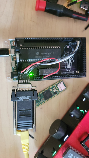
I used this to create JSON CPU tests for the 8080 and V20 CPUs. You can find those here:

http://github.com/singlestepTests/8088/
http://github.com/singlestepTests/V20

These test suites include 10,000 executions of each opcode, including undefined opcodes, capturing the entire bus state of each instruction.

These can be used to data-mine statistics about instruction execution, flag usage, or verify an emulator's accuracy.

GitHub - SingleStepTests/8088: A Hardware-Generated JSON CPU Test Suite for the Intel 8088

A Hardware-Generated JSON CPU Test Suite for the Intel 8088 - GitHub - SingleStepTests/8088: A Hardware-Generated JSON CPU Test Suite for the Intel 8088

GitHub

The only reason this works is that the 8086 and the 8087 were designed as full coprocessors. The 8087 maintains an identical copy of the CPU's prefetch instruction queue.

To do so, the CPU must tell the 8087 when it reads from the queue. It has a 2-bit status value for this purpose.

So by detecting code fetches, and monitoring the queue status lines, we can track the contents of the instruction queue ourselves - and thus, we know exactly what instructions are executing on the CPU and when each begins.
I've recently been exploring the NEC V20's 8080 emulation mode. So I expanded the client software to support executing 8080 code - it will enter emulation mode via BRKEM, execute your program, execute RETEM, then dump the final register state.

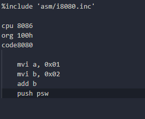
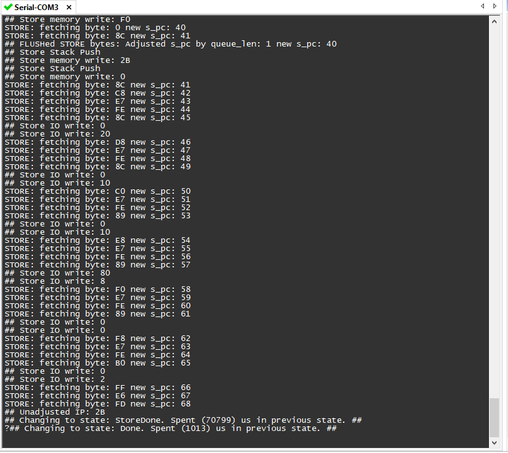
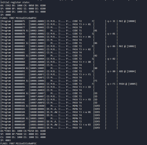
Here's what that looks like.

Here we perform 1 + 2 and then PUSH PSW to capture the result and flags.

If you look carefully at the end you will see the accumulator pushed to the 8080's stack via <- w 03

The hex digits in brackets represent the contents of the instruction queue. You can see it fill with ED FD at the end - this is the RETEM instruction being fed to the CPU to exit emulation mode when our program is complete.

I found this very convenient import for NASM that allows us to write 8080 code, so I didn't really have to do anything except import it.

https://github.com/BinaryMelodies/nasm-i8080

GitHub - BinaryMelodies/nasm-i8080: Intel 8080 mnemonics for NASM

Intel 8080 mnemonics for NASM. Contribute to BinaryMelodies/nasm-i8080 development by creating an account on GitHub.

GitHub
This is the program source.
We need to PUSH PSW at the end of our program to capture the 8080-mode flags. The RETEM instruction that returns us to native mode pops the native-mode flags that BRKEM pushed, so we lose them otherwise.

I hope to be able to add tests for the V20's 8080 instruction set to my V20 test suite.

It will be a bit awkward as you'll have to analyze the bus states to check the flags, but, maybe I can do a little post-processing magic to extract them for you and add them to the JSON.

This board theoretically supports the 8086 and V30 as well. I just made a lot of assumptions about an 8-bit data bus and byte-sized code fetches, so rewriting everything for 16-bits will be a bit of a job.
The same technique should also work for the 188 and 186, as they were compatible with the 8087, and thus expose the same queue status lines that give us complete control.
Unfortunately, the 80287 was a very different design, and so the 286 lacks the queue status lines that were so useful for controlling a CPU with an Arduino.

I still have some ideas - if the first thing we do after resetting the 286 is set the trap flag, then we should be able to detect execution of the trap handler as our instruction boundary.

This will of course slow things down incredibly, but I'm not sure what other option there is.

But if that method works, we could in theory even do this with a 386. There was a CMOS 386 designed for embedded devices with a 16-bit data bus, the 386 EX.

There are just barely enough pins on an Arduino GIGA to connect everything.

Someone smarter than me might consider using an FPGA or such. But that stuff is like voodoo to me.