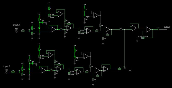
one hundred internet points if you can successfully guess what this circuit does, and how.

three hints:

1: it's pretty weird.

2. the inputs and outputs are no more than a couple tens of kilohertz (and are not a fixed frequency - the values shown in the sim below are arbitrary)

3: it only works in a real circuit and if you simulate this you will not see it doing the weird thing.

UPDATE: we have a winner. solution is here: https://chaos.social/@gsuberland/113921571918206983

Graham Sutherland / Polynomial (@[email protected])

I'm not even sure how to properly describe this. "nonlinear modulating low-pass filter", I guess? the core of it is that the MOSFET is a big power FET with a ton of Cgs. combined with the 220k resistor, you get a low-pass filter. the channel A voltage is adjusted to keep the MOSFET sub-threshold. except the really evil part of this is that the MOSFET's gate capacitance is dependent on Vds. so channel B modulates Vds, adjusting the filter's cutoff frequency.

chaos.social
anyone who asks an LLM is instantly disqualified and also loses my respect.
ok, a few of you have gotten very close so I'm going to provide a bit more help

alright, let's go with one final hint that's REALLY going to bake your noodle.

the MOSFET never turns on. at all.

nick (@[email protected])

@[email protected] @[email protected] uh, dang, I was working on the idea that the power rail was sagging ... ok so this has to be something to do with the capacitance of the depletion region varying with V_DS and thus turning that mwahaha bit into a swept filter

Aus.Social

I'm not even sure how to properly describe this. "nonlinear modulating low-pass filter", I guess?

the core of it is that the MOSFET is a big power FET with a ton of gate capacitance (Cgs). combined with the 220k resistor, you get a low-pass RC filter. the channel A voltage is adjusted by the opamps to keep the MOSFET sub-threshold.

except the really evil part of this is that the MOSFET's gate capacitance is dependent on Vds. so channel B modulates Vds, adjusting the filter's cutoff frequency.

I have literally no idea what this sounds like but I'm going to build it and find out.
another fun detail is that if you use a trench FET the Cgs has a very nonlinear drop as Vgs increases, whereas if you use a planar FET the Cgs is a fair bit more linear.
Weird Units (@[email protected])

coulombs per MOSFET

chaos.social
this isn't even the most cursed idea I have for abusing MOSFET properties. you can get into far weirder territory with SiCFETs, for example: https://chaos.social/@gsuberland/113924986156295201
Graham Sutherland / Polynomial (@[email protected])

one of the other evil tricks I want to try abusing with lesser-known FET behaviours is utilising subthreshold hysteresis in SiCFETs as a distortion effect. SiC has this odd property where the "history" of charge flow on the gate modifies the Vgs behaviour, moving the Miller plateau and threshold voltage depending on whether you were charging or discharging the gate, and how deep into the subthreshold region you went. the magnitude of the effect is also altered by Vds.

chaos.social
@dysfun I do have bagels and, at least in my mind, they are glowing like a pickup in a game.
@gsuberland using something like IXTN660N04T4 you’d even be able to get a useful amount of apparent capacitance there. IXTN660N04T4 has almost a microcoulomb of gate charge.
@jaseg yeah infineon have some chunkybois too, and some wide SOA ones with weird transfer curves (presumably because they're combination trench and planar)

@gsuberland

oh that's gonna sound real funky

@gsuberland yeah i figured that you're using the FET as a modulator but it wasn't completely clear for what purpose
@gsuberland so it should just be a scaled and shifted 50hz sine? the mosfet looks like its doing, well, not much since all you'd see there is gate capacitance? or is that *exactly* what its doing and the parasitic capacitance is making it act as a filter? would be very scuffed but i only have a basic understanding of electronics so uhhh not sure
@gsuberland oh the answer toot did not federate, but it was capacitance afteralll, crazy circuit! didn't know that much about depletion region stuff but am glad to have learnt a bit more about it :>

@gsuberland
Bloody ring modulator ...

Bloody phase comparator ...

You are trying to make me buy that arbitrary waveform generator ...

@gsuberland oh, I thought you meant this in general, not just specific to this thing here 😅

@gsuberland

hm. that looks like some modular synth nonsense.

@munin you are within the ballpark, but the devil is in the details :)
Before you continue

@grumpasaurus @gsuberland There is no frequency dependent components in the op-amp feedback. So I don't think a filter is correct.

I only see resistors and gain stages so it might do something to add signals together

@grumpasaurus @gsuberland Well I was wrong. The FET was the filter capacitor.

@gsuberland two wild guesses:

1. Microphone preamp with built in 'push to talk'

2. Microphone preamp with built in ANR

@gsuberland hopefully you will share both the answer and how you came up with the damn thing eventually?

@Lunaphied naturally. it's too cursed not to talk about :D

(I'm also going to build it)

@gsuberland
Something about letting bursts of 1kHz through at 50Hz using the gate protection diodes in the FET ...
@zl2tod no but you are looking in the right area

@gsuberland two distinct stages of ... negative feedback-loop op-amps with some sort of clipper ahead of it and a mixer after it and I get lost after that. But the real question is what happens when you take the weird morphed signal output of each of these similar-but-different-frequency circuits and connect them together via that N-channel MOSFET looking thing (?) at the output stage of the "B" circuit.

OOf. I wanna know what it sounds like! Probably some weird envelope of the high freq circuit being modulated by the same but 1/50th slower pattern of the "B" circuit via the FET.

BAH!

@gsuberland I don't know why (I can't really read circuits), so this is a deduction:

It somehow looks like a really feed-forward, feedback slew limiter. With the purpose of noise or distortion reduction?

Which could be useful for FM modulation?

@gsuberland is it a modulator of some sort? Coupled via the Cgs on that fet?
@phenidone ooooooh you're VERY close there.

@gsuberland I dunno. Looks kind of like a quadratic multiplier ("mixer" in the RF sense not the audio sense) around the fet but that signal doesn't get coupled out in the way I would expect.

Maybe a more dramatic effect like a robot-voice vocoder kind of thing?

I am limited by 5 hours of sleep and blinking at this over hotel breakfast, and also being dumb.

@phenidone "audio effect" would be in the right range.

I have posted a further hint:

https://chaos.social/@gsuberland/113921423149098863

Graham Sutherland / Polynomial (@[email protected])

Attached: 1 image ok, a few of you have gotten very close so I'm going to provide a bit more help

chaos.social
@gsuberland It plays the solo from "Cherub Rock."

@gsuberland my complete uninformed opinion trying to brute force it by sight is a feedback loop? But...it's asynchronous.

At least it looks like it's not 1:1, so increases incrementally?

@gsuberland are those resistors with two values trim pots? Also the values that read as just 10, are those 10 ohm or a typo for 10kOhm?
@kwayk42 just 10R, and yes they're potentiometers.
@gsuberland I'm going to guess that this circuit is what gave Furby a soul
@gsuberland
Not an answer (and I'm not an analog magic sorcerer), but the key thing is probably in these constant (and small) voltage buffers which will behave quite different depending on their type (RtR? Unipolar power? Which type of output?). Could be quite a lot of things including oscillations possible only with the power bus feedback/crosstalk.
@tyx nope, opamps are jellybean RRIO and don't do anything magic.
@gsuberland My first thought is, someone has been reading Douglas Self again.
@gsuberland Okay what the actual f***is up with that mosfet?

This isn't a Douglas Self meticulously engineered audio circuit, you're doing something utterly eldritch with the inherent substrate diode and/or gate capacitance.