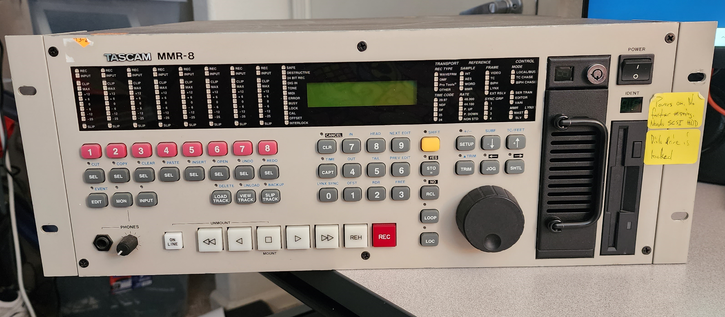
check out this wackiness in a removable hard drive sled inside a TASCAM MMR-8: It has a key lock, but the key lock doesn't lock the door, as you'd expect. Instead the lock is just a switch, and it communicates back with some board, which controls a solenoid to unlock the door. Now that's some paranoid over-design!
heh. The manual lists the approved hard drives for use with it.
I guess none of the letters in "SCSI" are "standard"!

 jo
jo


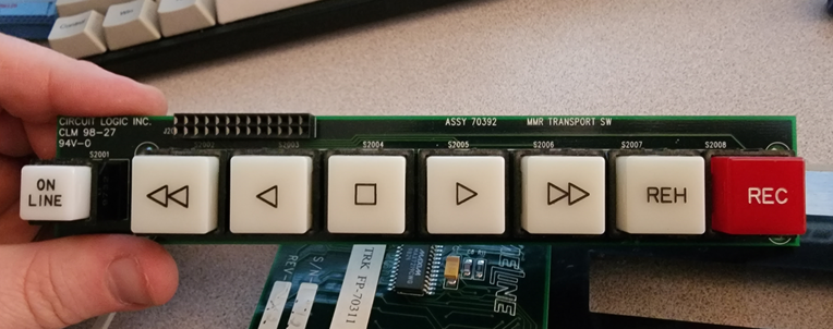
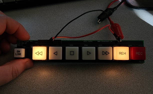
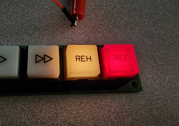
 Reh!
Reh!