Very happy about this.
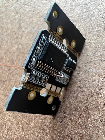
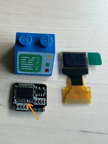
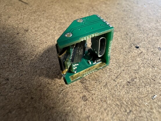
Here’s the bare circuit
I guess I’m just going to work my way through then.
Lots of people have asked, so: processor is a STM32F030F4P6 (Cortex M0, 16K flash, 4K ram), screen is a QT1306P82 (0.42" OLED).
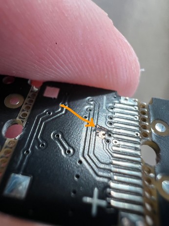
I haven't shared the schematic because it contains an error; you need to rework the boards to route a spare gpio to the screen. This involves drilling a 0.3mm hole through one of the pads, making a break in the ground plane, and soldering a little piece of wire through.

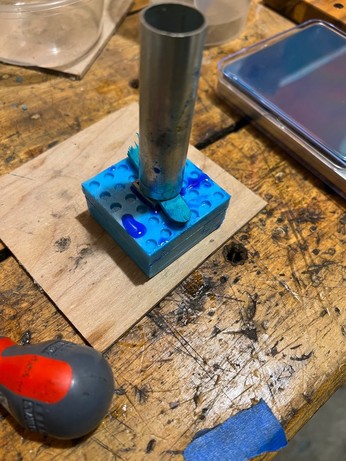
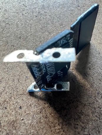
Putting together another brick. These battery contacts are the hardest part of the build.
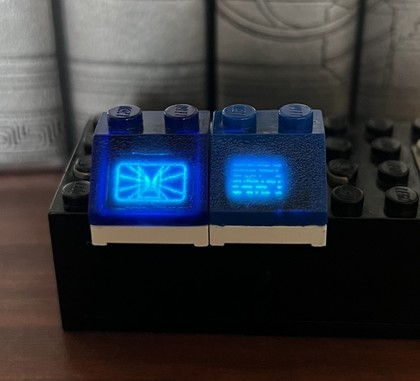
While that one cures, I added the trench run and got capacitive touch working in the studs.
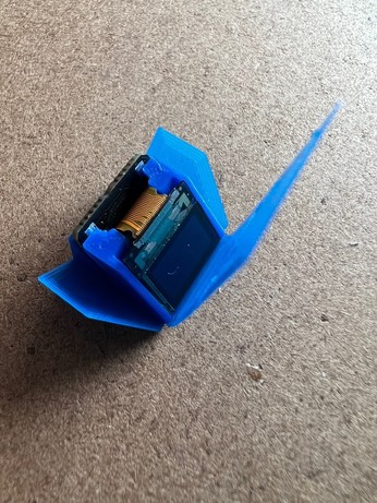
The new one is more opaque and a closer match to Lego Blue. I also painted the edges of the screen with black lacquer, which got rid of the glowing surround. It’s a very fiddly construction. If I’m going to make more, I need to work on tooling.
@ancientjames I realise this isn't news to you, but these are just amazing! 😁
@ancientjames may I ask how you made the contacts on the bottom of the brick? Are they simply wire that presses against the contacts in the side of the studs?
@ancientjames oh is it the side PCBs making contact via exposed pads? https://mastodon.social/@ancientjames/109244761058481795
@ancientjames Wow, that is really impressive!🤯
@ancientjames Wow -amazing work! 🤯
@ancientjames if you ever found away to mass produce these I would buy a half dozen they are amazing!
@ancientjames Thanks for sharing - this is such a cool project!
@ancientjames This is so amazing! 🤯
Submit this video to Lego if you are looking for a job : )
Submit this video to Lego if you are looking for a job : )
@ancientjames this is the kind of stuff that if someone asked me if it was possible I'd tell them no. Awesome work.
@ancientjames
I can't even imagine soldering components that small, let alone drilling a microscopic hole in a microscopic pad to pass a microscopic wire! 😯 Nice job!
I can't even imagine soldering components that small, let alone drilling a microscopic hole in a microscopic pad to pass a microscopic wire! 😯 Nice job!
@ancientjames I do this professionally and am plenty impressed at drilling 0.3mm holes for a kludge. The result is beautiful.
@smellsofbikes It was almost worth getting it wrong just for the satisfaction of fixing it.
@ancientjames I love a satisfying pcb save with a righteous board mod. I'm the person who drills and mills mods on our automated test boards at work and it's a superhero feeling to make a $20k board start functioning.
(TIL when you lay out a big board do a soldermask cutout and put copper numbers on each layer so you can hold it up to a light and see if the Fab house stack up matches what you designed as sometimes they swap for impedance matching and that's a big hassle for hitting midlayers)
(TIL when you lay out a big board do a soldermask cutout and put copper numbers on each layer so you can hold it up to a light and see if the Fab house stack up matches what you designed as sometimes they swap for impedance matching and that's a big hassle for hitting midlayers)
@ancientjames
This is all cool and charming and :ablobsmilehappy:
This is all cool and charming and :ablobsmilehappy:
@ancientjames This is just amazing. I am assuming that the lower brick is your work. Eager to see more!
@ancientjames
This is awesome!
This is awesome!