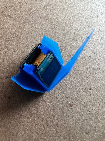
Very happy about this.
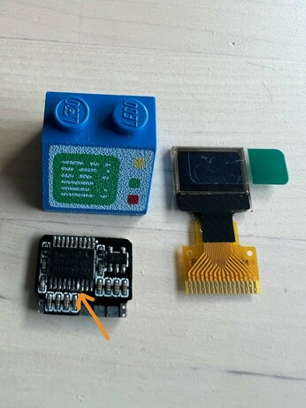
Here’s the bare circuit
I guess I’m just going to work my way through then.
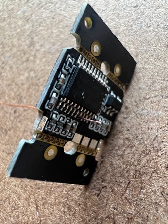
Lots of people have asked, so: processor is a STM32F030F4P6 (Cortex M0, 16K flash, 4K ram), screen is a QT1306P82 (0.42" OLED).
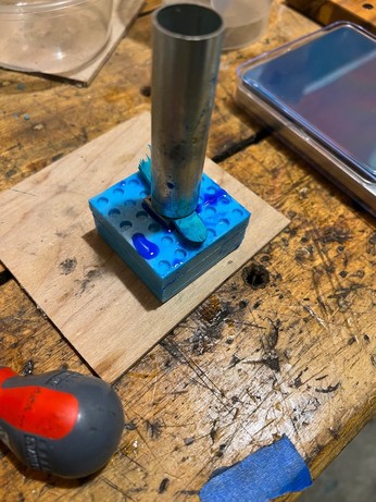
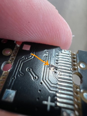
I haven't shared the schematic because it contains an error; you need to rework the boards to route a spare gpio to the screen. This involves drilling a 0.3mm hole through one of the pads, making a break in the ground plane, and soldering a little piece of wire through.

@ancientjames I do this professionally and am plenty impressed at drilling 0.3mm holes for a kludge. The result is beautiful.
@smellsofbikes It was almost worth getting it wrong just for the satisfaction of fixing it.
@ancientjames I love a satisfying pcb save with a righteous board mod. I'm the person who drills and mills mods on our automated test boards at work and it's a superhero feeling to make a $20k board start functioning.
(TIL when you lay out a big board do a soldermask cutout and put copper numbers on each layer so you can hold it up to a light and see if the Fab house stack up matches what you designed as sometimes they swap for impedance matching and that's a big hassle for hitting midlayers)
(TIL when you lay out a big board do a soldermask cutout and put copper numbers on each layer so you can hold it up to a light and see if the Fab house stack up matches what you designed as sometimes they swap for impedance matching and that's a big hassle for hitting midlayers)