I’ve always liked the idea of mathematics, algorithms and their application to music, so a Euclidean Sequencer has been on my list of things “to do” for a while.
This is my take on how to build one from an Arduino. This post focuses on the code and algorithms – some more useful hardware will come along later maybe in a future post.
- Part 1 covered all the theory and main functions of the code.
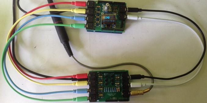
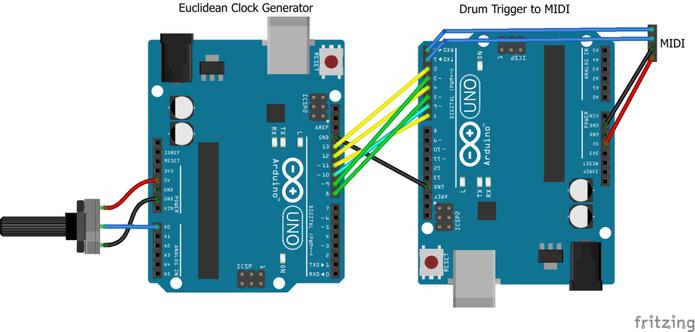
- Part 2 included some hardware suggestions for connecting it to other devices.
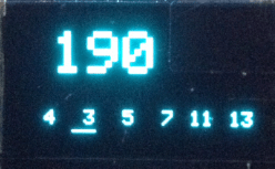
- Part 3 added a rotary encoder and I2C display and demonstrated by Arduino Clock Generator Shield PCB.
- Part 4 reimplements HAGIWO’s original with a few tweaks and updates.
Also see the Arduino Clock Generator Shield PCB design.
But before I get stuck in, first let me call out two very comprehensive and well implemented and documented DIY Arduino Euclidean Sequencers that do so much more than I’m thinking of doing:
Warning! I strongly recommend using old or second hand equipment for your experiments. I am not responsible for any damage to expensive instruments!
These are the key tutorials for the main concepts used in this project:
If you are new to Arduino, see the Getting Started pages.
Introduction and Background
The basic idea is that splitting a number of steps in a sequence up into equal, but irregular timings, will generate interesting polyrhythms.
The “Euclidean” part comes from the original paper that recognised a similarity between two approaches to splitting up the sequence and a range of rhythms that were in use around the world. The trick is working out how best to evenly distribute the beats across the sequence. Easy when you have 4 beats across a 16 step sequence, but not so easy for 5, 7 or 13 (for example).
It turns out (see the references above) that there is a relatively simple algorithm to achieve this. In pseudo-code it looks like this:
steps = 16
beats = 7
counter = steps-beats OR 0 if beats = 0
FOR EACH step:
counter += beats
IF counter >= steps THEN this step is ON
ELSE this step is OFF
counter %= steps
Basically, we keep adding “beats” to a counter and every time the counter overflows the total number of steps, we log a beat to be played, and then have the counter wrap-around.
Note: ideally we want the counter = steps at the start to ensure our first step is ON, but as the first thing we do is counter += beats, the counter has to be set to steps-beats to achieve this. The exception is if for some reason beats is 0, then we need all outputs to be zero, so need the counter to be less than steps (so I just set it to 0 directly).
Here is how the above example plays out for 7 beats across 16 steps for each of the 16 steps:
Step Counter Output
0 16->0 1
1 7 0
2 14 0
3 21->5 1
4 12 0
5 19->3 1
6 10 0
7 17->1 1
8 8 0
9 15 0
10 22->6 1
11 13 0
12 20->4 1
13 11 0
14 18->2 1
15 9 0
So the optimal sequence for playing 7 beats evenly across 16 steps of a sequencer is:
1001 0101 0010 1010
OR
100 10 10 100 10 10 10
This algorithm can thus be used to work out any combination of beats up to a specific number of steps.
Here is some code for an Arduino that will output to the serial monitor all the sequences for a number of steps, in the form of a C language structure that can then be pasted into another Arduino sketch.
#define STEPS 16
void setup() {
Serial.begin(9600);
for (int i=0; i<=STEPS; i++) {
EuclideanPattern(STEPS, i);
}
}
void EuclideanPattern (int steps, int beats) {
if (beats > steps) return;
int cnt = 0;
if (beats > 0) {
cnt = steps - beats;
}
Serial.print(" {");
for (int i=0; i<steps; i++) {
cnt += beats;
if (cnt >= steps) {
Serial.print("1");
} else {
Serial.print("0");
}
if (i < steps-1) {
Serial.print(",");
}
cnt = cnt % steps;
}
Serial.print("}, \/\/ ");
Serial.print(beats);
Serial.print("\n");
}
void loop() {
}
Which gives the following output – all the Euclidean pattern combinations for a 16-step sequence.
{0,0,0,0,0,0,0,0,0,0,0,0,0,0,0,0}, // 0
{1,0,0,0,0,0,0,0,0,0,0,0,0,0,0,0}, // 1
{1,0,0,0,0,0,0,0,1,0,0,0,0,0,0,0}, // 2
{1,0,0,0,0,0,1,0,0,0,0,1,0,0,0,0}, // 3
{1,0,0,0,1,0,0,0,1,0,0,0,1,0,0,0}, // 4
{1,0,0,0,1,0,0,1,0,0,1,0,0,1,0,0}, // 5
{1,0,0,1,0,0,1,0,1,0,0,1,0,0,1,0}, // 6
{1,0,0,1,0,1,0,1,0,0,1,0,1,0,1,0}, // 7
{1,0,1,0,1,0,1,0,1,0,1,0,1,0,1,0}, // 8
{1,0,1,0,1,0,1,0,1,1,0,1,0,1,0,1}, // 9
{1,0,1,0,1,1,0,1,1,0,1,0,1,1,0,1}, // 10
{1,0,1,1,0,1,1,0,1,1,0,1,1,0,1,1}, // 11
{1,0,1,1,1,0,1,1,1,0,1,1,1,0,1,1}, // 12
{1,0,1,1,1,1,0,1,1,1,1,0,1,1,1,1}, // 13
{1,0,1,1,1,1,1,1,1,0,1,1,1,1,1,1}, // 14
{1,0,1,1,1,1,1,1,1,1,1,1,1,1,1,1}, // 15
{1,1,1,1,1,1,1,1,1,1,1,1,1,1,1,1}, // 16
This might typically be used something like the following:
#define PATTERNS (STEPS+1)
const uint8_t patterns[PATTERNS][STEPS] = {
... data goes here ...
};
int pattern = 7; // Choose pattern between 0 and 16 inclusive
for (int step=0; step<STEPS; step++) {
if (patterns[pattern][step]) {
// Play
} else {
// Skip
}
}
In a sequencer we’d probably want to include options for adjusting the starting point in the sequence too, but this is the basics of what is to follow.
Parts list
- Arduino Uno R3
- 10K potentiometer
- Optional: LEDs and associated (e.g. 220Ω or 1K) resistors
- Breadboard and jumper wires
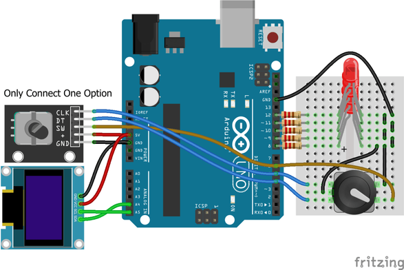
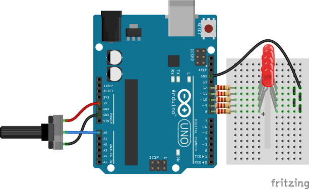
The Circuit
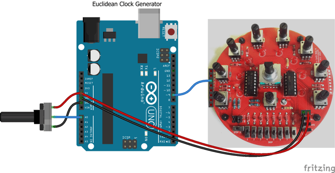
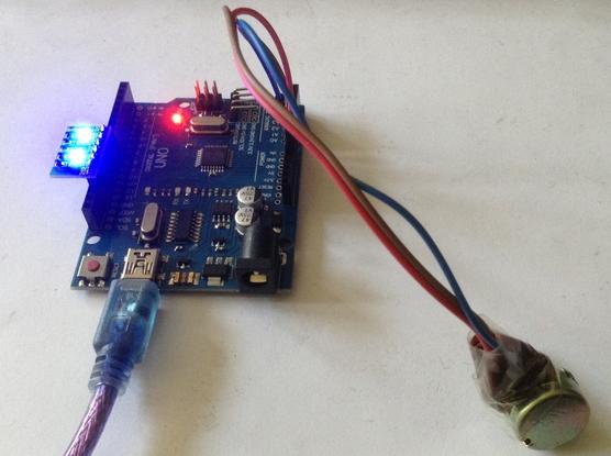
A potentiometer to control the tempo is connected to A0. There are five clock outputs on D8-D12. To illustrate the functioning of the clock patterns, each output is connected via a resistor to an LED and then onto GND, but this is optional. It just makes the output visible.
The outputs will be a 5V signal, but it is not buffered in anyway.
It might be possible to use the signal “as is” depending on what it is driving, but in order to avoid damaging the Arduino what is connected to it must not draw more than around 20mA of current.
In order to avoid damaging the thing you want to connect to it – my strong recommendation is not to connect it at all.
This is not a completely usable circuit, it is meant just to be proving the software.
The Code
The idea is to use a timer to provide a constant “TICK” for the system. The TEMPO (set with the pot) will determine how many TICKs are in each STEP. And the Euclidean algorithm will determine which STEPs have a GATE on and which are off. This will be supported for a number of GATE outputs allowing different Euclidean patterns to be present on each output.
Things that are still missing that would make this a possibly useful sequencer are:
- There is no way to select the pattern for any GATE output.
- There is no hardware buffering or electronic protection on the outputs – they are just a microcontroller GPIO logic output so for an Arduino Uno R3 this means they are limiting to being to provide around 20mA of current.
- There is no visual display or feedback on what is happening, but the LEDs are optionally provided as a temporary output.
- It might be useful to be able to get its main clock signal from an external source.
There are several sections within the code:
- GATE IO and Euclidean patterns definitions.
- Timer routines.
- Sequencer GATE handling routines.
- Standard Arduino setup() and loop().
Taking each in turn.
The GATE IO and Euclidean pattern definitions list which GPIO pins are being used and has the definition of the 17 Euclidean patterns for all combinations of 16 STEPS (including for 0 steps).
I’ve also included a function to essentially answer the question “is this step in this pattern on or off”.
The patterns are stored in the Arduino’s PROGMEM memory area as they are constant and this will conserve the Arduino’s limited dynamic memory. But this means to get access requires the use of pgm_read_byte() and will be slower than just reading memory directly.
#define GATES 5
int gatePins[GATES] = {8,9,10,11,12};
#define STEPS 16
#define PATTERNS (STEPS+1)
#define DEFAULT_PATTERN 4
const uint8_t patterns[PATTERNS][STEPS] PROGMEM = {
... data here ...
};
bool patternStepOn (unsigned pattern, unsigned step) {
int stepstate = pgm_read_byte(&(patterns[pattern][step]));
if (stepstate) {
return true;
} else {
return false;
}
}
I’m using the TimerOne library to provide a regular TICK for the system. I’m aiming to support 4 STEPS per BEAT with a TEMPO range of around 20 BEATS per minute up to around 240 bpm.
Getting a little hand-wavy, this means that the shortest STEP interval has to support 240*4 = 960 STEPS per minute or 16 STEPS a second, giving it a period of around 63mS.
The longest STEP interval will be around 80 STEPS per minute or 0.75 STEPs a second which is around 1.3 seconds per STEP.
Given the above, I’ve gone for a 10mS TICK from the TimerOne library and a minimum TEMPO of 3 TICKS per STEP. I’ll scale an Arduino pot reading to a value between 0..127 which means the number of TICKS per STEP will be between 3 and 130 giving a range of 30mS to 1300 mS.
#define TIMER_PERIOD 10000 // Period in uS
#define TEMPO_MIN 3 // 30mS minimum
void sequencerSetup (void) {
Timer1.initialize(TIMER_PERIOD);
Timer1.attachInterrupt(sequencerLoop);
}
The sequencerLoop() function will be responsible for working out what core sequencer action is required according to the TEMPO and which STEP we’re on.
tempoTickCounter starts with a value between 3 and 130
sequencerLoop():
tempoTickCounter--
IF tempoTickCounter == 0:
outputGates()
updateGates()
reset tempoTickCounter back to its starting value
I’m splitting up the output and update of the GATE values from the sequencer as I’m anticipating the updating taking a bit longer. This means that each update will get the values ready but they will only be reflected in the GPIO at the start of the next TICK. The idea is that any jitter that might have been introduced due to the code calculating values and retrieving them from PROGMEM will be “soaked up” between TICKs and the actual transitions will remain accurate to the 10mS TICK resolution.
There is one other consideration though. When generating GATE signals they are meant to be HIGH as long as an output is required. But if there are consecutive STEPS then the GATE signal won’t change – it will remain HIGH between STEPS. This means that anything being driven by the sequencer won’t see a new transition between STEPS.
I’ve considered two options here:
- Swap to TRIGGERS rather than GATES. This means each STEP is simply a TRIGGER pulse HIGH for a fixed length (e.g. 1 10mS TICK) rather than HIGH for the whole STEP.
- Ensure there is a small gap (e.g. 1 10mS TICK) between each STEP to ensure the GATE stops and restarts.
Actually, I’ll add a TRIGGER output shortly, but I still want the option for a GATE, so to achieve this, I ensure that all GATES are turned off for the last TICK before the TEMPO dictates the next GATE update. I don’t know if 10mS will be enough yet, but some experimentation with some proper hardware should give a pretty clear idea, but that is a task for another time.
In code this means adding an additional IF clause as follows:
IF tempoTickCnt == 1:
clearGates()
In order to support either GATE or TRIGGER, I need a way to essentially invert the GATE behaviour and have the TRIGGER HIGH for just one TICK. I’ve included a #define to choose one or the other and swap the code around accordingly.
The final sequencerLoop() is thus as follows:
tempoTickCounter starts with a value between 3 and 130
sequencerLoop():
tempoTickCounter--
IF tempoTickCounter == 0:
IF TRIGGER MODE clearGates()
IF GATE MODE outputGates()
updateGates()
reset tempoTickCounter back to its starting value
IF tempoTickCnt == 1:
IF TRIGGER MODE outputGates()
IF GATE MODE clearGates()
The TRIGGER is fixed to a single TICK, so 10mS, but the TICK is easily adjusted if a longer TRIGGER is required. I suspect this is a lot simpler than coding for the TRIGGER to stay on for several TICKS.
The sequencer GATE handling routines will set up the Arduino’s digital IO for GATE outputs.
int stepCnt; // Current step count
int gateStep[GATES]; // Current step output value for this GATE
int gatePatterns[GATES]; // Which pattern is used for this GATE
void setupGates () {
for (int i=0; i<GATES; i++) {
pinMode (gatePins[i], OUTPUT);
digitalWrite(gatePins[i], LOW);
gatePatterns[i] = 0;
gateStep[i] = 0;
}
stepCnt = 0;
}
void clearGates () {
for (int i=0; i<GATES; i++) {
digitalWrite(gatePins[i], LOW);
}
}
void outputGates () {
for (int i=0; i<GATES; i++) {
digitalWrite(gatePins[i], gateStep[i]);
}
}
The main logic all happens in the updateGates() function which sets the values in gateStep[] for the next STEP to be “played” when the outputGates() function is next called.
void updateGates () {
stepCnt++;
if (stepCnt >= STEPS) {
stepCnt = 0;
}
for (int i=0; i<GATES; i++) {
if (patternStepOn(gatePatterns[i], stepCnt)) {
gateStep[i] = HIGH;
} else {
gateStep[i] = LOW;
}
}
}
The main Arduino setup() and loop() functions just have to call the appropriate setup functions for the different sections, set up the range of patterns required per GATE output by initialising gatePatterns[] and updating the reset value for the tempoTickCounter according to the value read from the potentiometer on A0.
Find it on GitHub here.
Closing Thoughts
I was struggling to translate the original paper on Euclidean rhythms over to an Arduino, and there didn’t seem to be much explanation out there on how it works, but I think I got there in the end.
I’ve not wanted to plug these signals into anything yet, so next I’ll work on some hardware (even it just a way to wire up some sync jacks) and attempt to actually get it working.
I might try to add a means of configuring a pattern for each GATE and some kind of visual output, but to be honest, nothing will beat the implementation already put together by HAGIWO, so I might end up just using that if want anything more sophisticated.
Kevin
https://diyelectromusic.com/2024/10/04/arduino-euclidean-gate-sequencer/
#arduinoUno #define #euclidean #gate #stepSequence