https://github.com/RightRudderLeftStick/OpenSource-VeryBigStick
Open Source project Very Big Stick finished adding rather sturdy rudder pedals. Requires a 3D printer.
https://github.com/RightRudderLeftStick/OpenSource-VeryBigStick
Open Source project Very Big Stick finished adding rather sturdy rudder pedals. Requires a 3D printer.
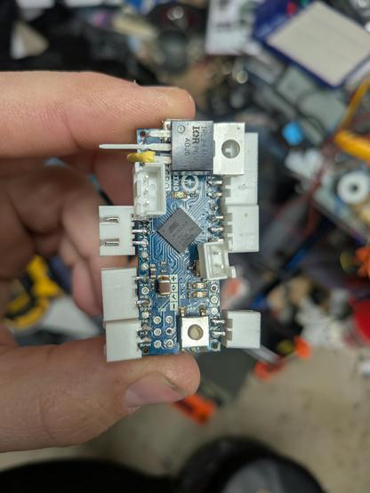
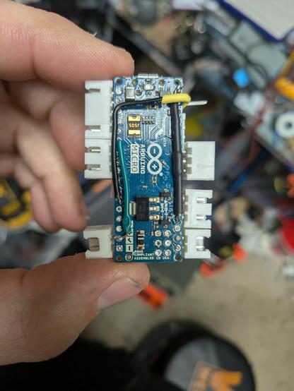
I repaired my old Thrustmaster rudder pedals. That’s the one I upgraded using an Arduino Pro Micro before (PeerTube, YouTube) to get rid of their old D-Sub connector so this device is really old and probably belongs into a museum. I doubt I’d get any replacement parts for this from the vendor nowadays.
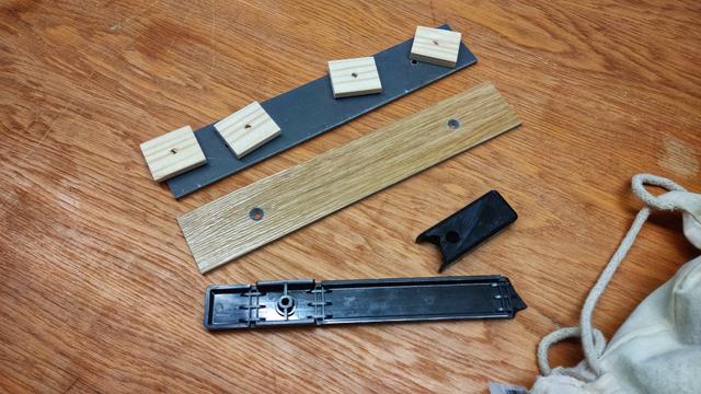
Their sliding beds are made of some sort of plastic and this started to become brittle over the years. When I noticed that one side was coming apart I found several more hair fractures so I had to stop playing with the pedals for a while.
Yesterday I went with one of the sliding beds to the Swablab, our local maker space, and considered cutting and milling new parts of wood, when a fellow maker suggested to use some leftover HPL pieces for the job.
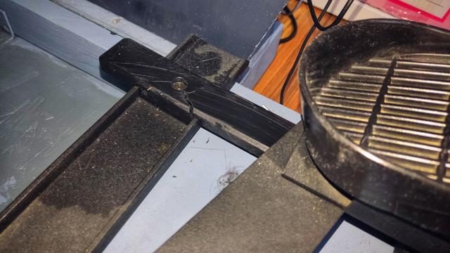
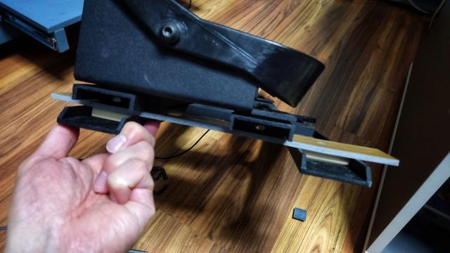
This was far less complicated compared to what I had in mind and I went for it. After a few minutes in the workshop I ended up with two new sliding beds that I mounted today. Worked like a charm.
I went with Liquid Moly LM47 for some lube, simply because I have a tube of that around from working on the car. That’s grease for stuff like bearings and probably overkill for the job.
Couldn’t be happier. The pedals are back into service and feel even better than before (probably thanks to the new grease) and I avoided once more going for expensive modern replacements. I’m also probably the only one with rudder pedals with wood aesthetic now 🤓
https://beko.famkos.net/2026/04/16/thrustmaster-rudder-pedal-repair/ #DIY #flightsim #homeCockpit #simpit #Swablab #Thrustmaster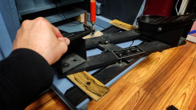
I'll miss my #HOTAS / #HOSAS / #SIMPIT / #DIY #Discord channels starting next month.
Anyone knows some alternative Spaces on #Matrix by chance?
I'm aware of https://matrix.to/#/#hotasdiy:matrix.org channel.
Edit: Getting somewhere: https://matrix.to/#/#aerospace-space:hacklab.fi
Moving my 🤓 Discord space here https://matrix.to/#/#bekomotion:matrix.org shutting down there.
Acronyms:
HOTAS = Hands on Throttle and Stick
HOSAS = Hands on Stick and Stick
SIMPIT = Simulation/Simulated Cockpit
#HomeCockpit #FlightSim #Joystick #Gamepad #Controller
♻️ 🙏

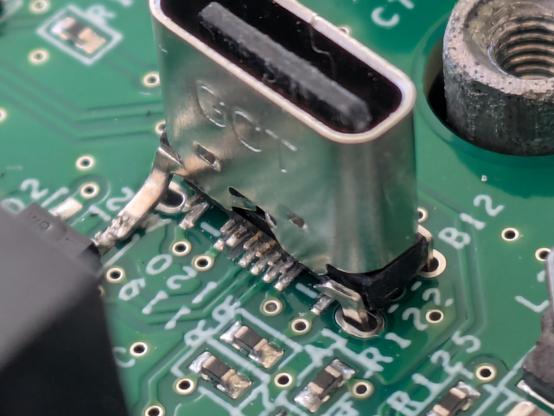
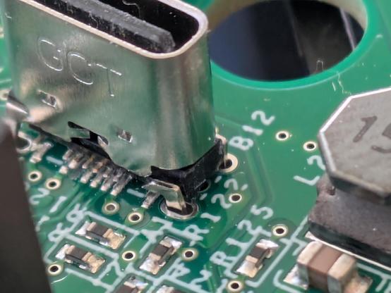
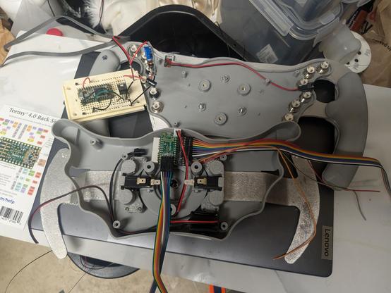
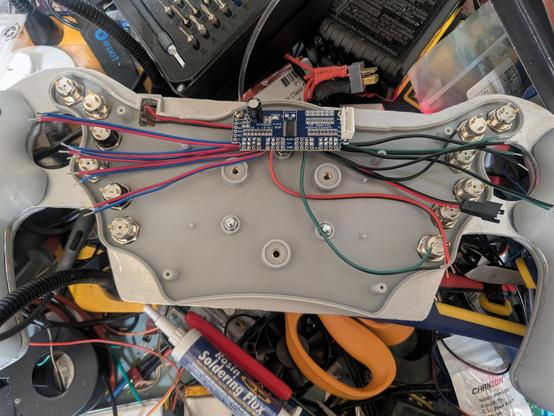
Okay, the new sub-brain should be ready to go. #simpit
Btw. If you're wondering if that mosfet is flicking you off? Yes. Yes it is. 🖕
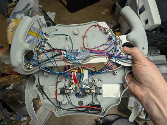
I don't understand why custom racing sim wheels cost hundreds of dollars, it can't be that hard to make right?
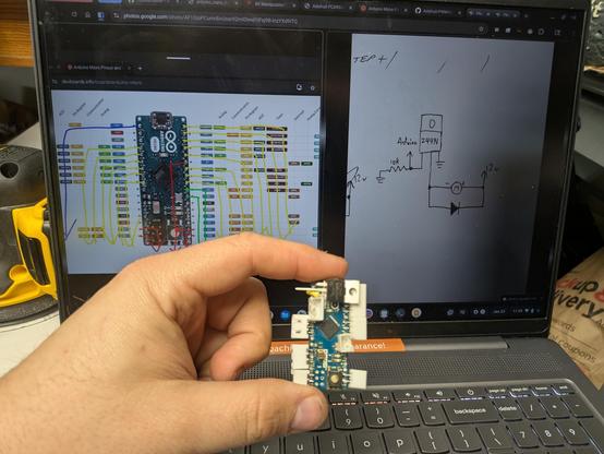
Making progress. I'm hoping to complete the wiring today and be able to start on the code. #simpit