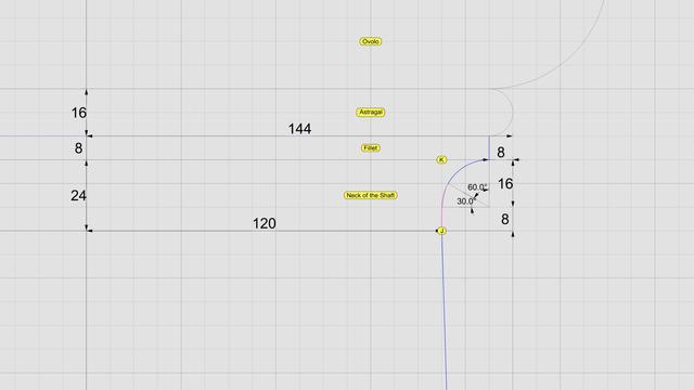
The neck is conceptually divided into three bands, each 1 part (8 units) tall. In the top 2/3, we draw a circular 90° arc with radius of 16 units, divide it into thirds, and discard the lower 30° portion.
Then, blend the lower end of the arc and upper end of the interpolated NURBS curve to create a new NURBS curve shown here in magenta. Zoom in, and you will see that it deviates slightly from the original 90° arc. This is because the blended curve is tangential to the 60° arc and the longer NURBS curve. When joined, the three sections form a smooth #continuouslyDifferentiable NURBS curve.
This level of precision is only needed for engineering work. If you just want a #charcoal #sketch, #draw in #ink, #paint in #watercolor, or even make #clay or #ceramic #basrelief, then you don't even need a #CAD program. A compass and protractor are sufficient. Just blend the shapes by hand as closely as you can. The imperfections, if any will be imperceptible.
This brings us back to the previous post. If you're not using CAD, how do you obtain the 8 points C through J using manual tools?
Look closely at the radiating lines, first of which passes through point B and the last one reaches point 8. An easy way to find the angle between these two lines is to use basic trigonometry.
Focus on the center of the arc, follow up to point 8, and then drop down vertically where the horizontal line is split at 120 units, and close back to the origin. This is a right triangle whose hypotenuse is the radius of the arc. The cosine of the angle between the base and the hypotenuse is 120/144 = 0.83333333. So the angle itself is arc cosine of 0.83333333, or 33.55730976°. For hand drawing, round it off to 33.6°. Then divide that into 8 parts of 4.2° each to plot points 1 through 8.

Splines (@[email protected])
Arcs and lines toil for #splines 2500 years ago, when they had neither computers nor #CAD tools, designers and architects relied on knowledge of algebra, geometry, and trigonometry for their daily work. It was a mere 350 years ago that Leibniz and Newton brought calculus as a new mathematical tool for design and engineering. Before computers arrived, artists, designers, and architects toiled with manual drafting tools to engineer breathtaking masterpieces. "Toil" is not an exaggeration to describe that endeavor, even though I suspect some of them really enjoyed what they were doing. #Scarlata compiled an entire book on #VignolaProportions with painstaking accuracy and high precision before there were calculators and spreadsheets, making it "easy" to convert from µ to physical units in both English and Metric systems, but the world has moved on, his work is forgotten, and nobody is thankful for his contributions. If you have a CAD tool, you need not toil. Simply draw an arc of radius µ = 144 that is centered on the #columnAxis and passes through point B. Then draw a vertical line parallel to the column axis at x = µ * 5/6, or 120 units. Use this line to split the arc and trim away the left portion of the arc. Next, divide the length of the remaining portion of the arc into 8 equal portions using your CAD tool to mark points 1 through 8 as shown. If your CAD tool is able to divide the leftover arc this way, you can just ignore the angular lines radiating from the center. Otherwise, I will show you how to use them as a fallback. Now look at point C, which seems like it is vertically above point B, but it is not. It is actually vertically above point 1. Draw 7 more vertical lines starting with point 1, then point 2, and so on. Mark point C at 192 units vertically above on line 1, D at 192*2 on line 2, E at 192*3 on line 3, and so on until you reach point J. Select these 8 points and use your CAD program to interpolate a free-form NURBS curve to fit these points.

