This was supposed to be a test print, but I think I’ll be keeping it. #LT6502b
Next will be the screen front bezel.


This was supposed to be a test print, but I think I’ll be keeping it. #LT6502b
Next will be the screen front bezel.
WOOT!
Sorted the bugs (intermittent framing issue when sending) and added TX_BUSY status bit.
Here you can see me checking connectivity and then connecting to a simple BBS (this is the console on my laptop).
I do think I'm getting buffer overflows on some servers (m68k one and a couple of others) but this one worked a treat!
So next I need to write a terminal emulator (which I am not looking forward to).

oOO, Getting closer to a working CPLD/WiFi modem for my 6502 Laptop
got a couple of bugs that are irritating.
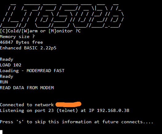
Here I'm connecting to a BBS using BASIC to send the ATDT command and then display what comes back from the modem.

Well a lot of work on #LT6502b today.
Now running at 10MHz (up from 7MHz), Keyboard now working and I can receive data from the WiFi Modem.
Next is making the CPLD transmit to the WiFi Modem.
Then trying to figure out why I can't run at 14MHz...
#Retrocomputing #6502
IT WORKS!!!
With a bit of effort I can now receive data from the UART on my keyboard controller, into the CPLD and read it form BASIC on my 6502 laptop revision b (slim version).
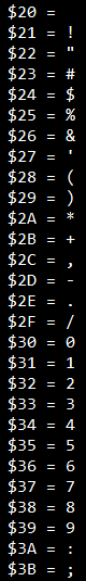
I've set the Keyboard controller to output characters from $20 to $7F, here you can see them being shown.
There is also a "new data received" status register too!
Well the CPLD UART is coming along, another big step... Now when it's done receiving a byte, it transfers it to a register, which can then be read at anytime by the CPU. So that the CPU doesn't read garbage if it tries to read mid transfer (double buffer).
more to do yet as I need two such registers and I also want the register to be cleared once it's been read, but this is BIG progress.
This is all done in WINCUPL, not VHDL/Verilog.
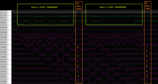
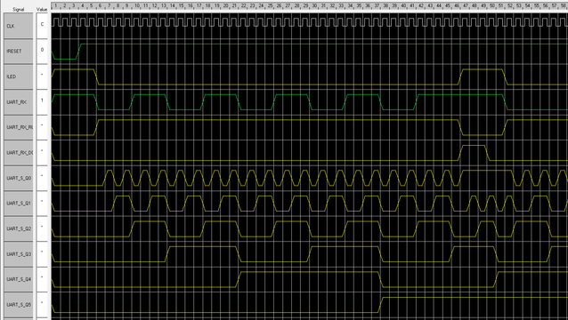
Ok, so, I have the next part working of my CPLD UART... it now populates a buffer, with the correct values!!
Green = serial in (LSB first),
Orange is parallel out (LSB at the bottom)
Next step is to transfer that to a register that can be read!
I will probably up my sample clock to 16x, as that seems like the common thing, and 4x may not be 100% reliable. But for simulation, 4x is enough.
Fun with WinSim.
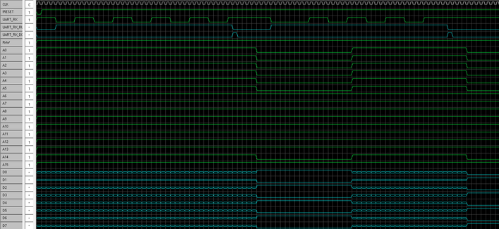
After much battling with dodgy tools from the 90s, I've now got two useful signals. One to start the UART receive and it's counter, and one to stop when the 10th bit is received.
Tomorrow, shift register to capture the bits.
I've been trying to get my KeyScan (ATMEGA644P) to output onto the 65c02 databus at the correct time and for the correct duration...
I don't think it's going to work, sometimes I get no data back, when I tweak the timing I somehow get a 16bit value back (impressive from an 8 bit CPU eh?).
So, I may have to put a UART into the CPLD, and "WinSim" doesn't seem to simulate properly. So it'll be try and keep trying until it works, or I run out of space.
Has anyone done a UART in a CPLD?