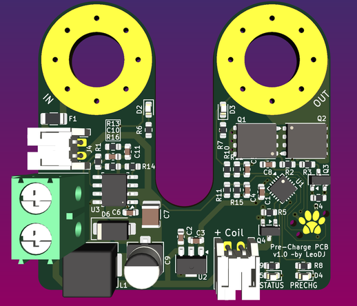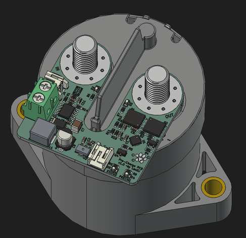
Currently in the process of designing the main power switch for #Torquee.
It needs to switch the 48V battery voltage at up to 500A.
I'll be using a EV200/GV200 contactor for this.
But I need a 12V supply and pre-charge circuit so I don't explode the contacts when trying to instantly charge ~8mF of input capacitance of the 2 #startergenerators to 50V in microseconds :D

So I'm designing this PCB, that'll screw on top of the cable lugs and connects to GND and actual switch input.
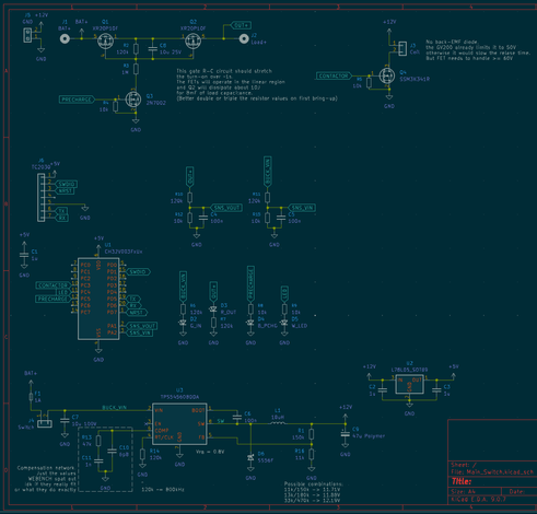
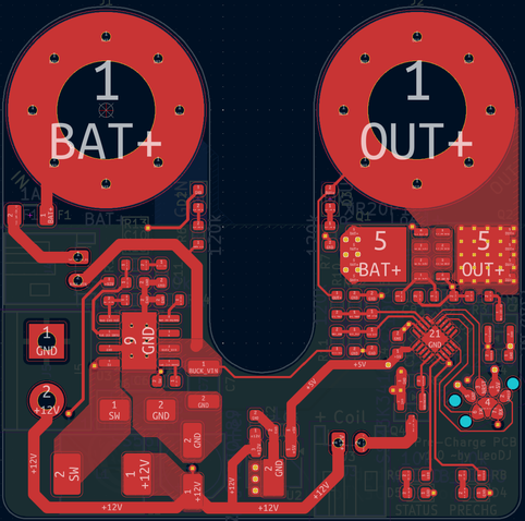
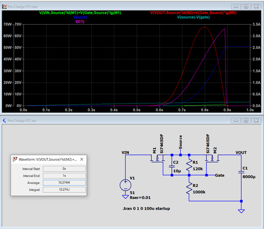
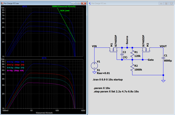
My planned approach is using a P-FET with a RC network at its gate so it does the pre-charging over a few 100ms in its linear region. What do you think?

I've simulated it in LTSpice and it seems to work ok and stay in the safe operating area of the given MOSFET.
(I've chosen a similar FET in LTSpice for a good model)

@LeoDJ I felt my butt clench a bit while reading 48V/500A. That's some serious current. Not sure I understand it correctly though - Is that full 500A current running through Q1 and Q2, or is that big tube thingy the contactor, and Q1 and Q2 are just required to provide enough switching juice for the contactor? I'm totally out of my depths here, but the labelling around Q1 and Q2 suggested to me that all of the current flows through them. And the PCB traces do not look 500A capable to me :D
@thunfisch Ye, that big tube thingy is the contactor. A Gigavac GV200, 500A 800V DC contactor to be exact.
It will conduct the main current between battery + and motor controller +.
But because motor controllers have quite beefy and low ESR input capacitors, if the contactor would simply make the connection when the input caps are empty, there would be many kiloamps flowing through not-quite-mated switch contacts, trying to charge the caps rapidly.
That's where the FETs come in. They pre-charge the input caps slowly and only then the contactor will be engaged.
The MCU is there to oversee that process. I.e. not engaging the contactor when it still senses a voltage difference that's too great, etc.
@LeoDJ Aaaah. I see. So your circuit is connected in parallel to the contactor, and the PCB just cleverly sits on top of the contacts for the contactor. Now it all makes much more sense to me. Seems like a clever design to me to put it on there, and check conditions for safely actuating the contactor.

@LeoDJ @thunfisch In EVs this is conventionally done with two set of contactors, one with a resistor in series for precharge and the main contactor that can carry the full current.

Tesla apparently did away with the precharge contactor by running the LV battery charger in reverse to charge the inverter input caps to battery voltage. One part less!

@LeoDJ the electric too big

cannot hold the electric

please stop

@LeoDJ you can't just run a fat pre-charge resistor in parallel with the contactor?

That's what we do on our #ppprs karts, but we have a manual contactor switch and wait for many seconds to watch the voltage meter go in to range. And we don't care about parasitic loss because we pull the batteries between races.

@poleguy Haha, cool solution :D
I *could*, yeah. But I wanted to go for this solution ^^
Mainly so I can leave the battery in, if I want to, because the plan is to have cable lugs screwed to the battery's contacts (it's meant for screwed connections).
Connectors for 500A get expensive and large *quick* :D

And also to have a switch that completely powers off the whole system should anything happen.

@LeoDJ that looks very elegant :D The common approach in formula student is a smaller precharge relay and a PTC resistor but there the rules forbid switching using semiconductors and we are running 600V ^^'
@jakob Thanks ^^
Yeah, at that voltage I wouldn't want to rely on semiconductors that like to fail short either :D
I also thought about a second relay + resistor but opted to go for this solution first ^^