
Over the Easter weekend, I had some time to follow @maehw 's instructions to build a DIY infrared tower to connect to the #lego #mindstorms RCX module (see here: https://github.com/maehw/DiyIrTower)

My original IR tower did not work anymore after 25+ years and I'm very grateful for this opportunity to re-activate this set.
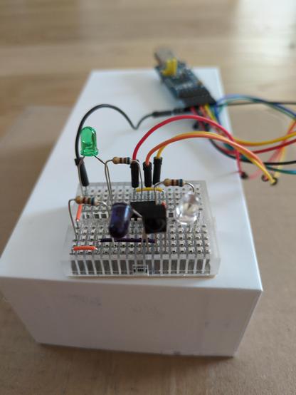
Here's a list of points at which I slightly got stuck. Maybe it's helpful for others who try to do it in a similar way:
(1) For the includes "<avr/io.h>" and "<avr/interrupt.h>" in the firmware it took me a moment to realized that the corresponding libraries are packaged in avr-libc.
(2) I didn't immediately understand that the "programmer" (ISP) is a dedicated piece of hardware. My brother-in-law then gave me an Arduino board to use it as the programmer. (The corresponding firmware is part of the examples to be found in the Arduino IDE.)
(3) While one can then use avrdude with Arduino as the programmer, the programmer "arduinoISP" is *not* the correct one for this purpose. The simplest option for me was to add the ATtiny as a board in the Arduino IDE (see instructions here: https://github.com/sleemanj/optiboot/blob/master/dists/README.md#installation--usage), and then use the avrdude binary and config files located in the (hidden) Arduino configuration folder. (The precise avrdude syntax used by the Arduino IDE by activating "show verbose output during upload" in the preferences).
(4) It took me a while to figure out that it's necessary to give Chromium on Ubuntu (which is a snap package) special permissions to use the serial port by running "sudo snap connect chromium:raw-usb". (During the installation of Arduino ID, it was also suggested to add my user to the group "dialout", but I'm not sure if this was really necessary).
(5) I had to play a little bit with the angle of the IR LED before the connection with the RCX module was established successfully.
(6) For ordering parts: The board to which the electronic components are pinned is called a "breadboard". The wires making connections on the board are called "jumper wires".
@beta3 wow, thank you very much for that important feedback. When I find time, I'd like to add this beginner friendly info to the README in the repo. In case you're interested in PCB Rev. 1 (with some minor hardware), I can also send you some bare PCBs in case you're located in DE/AT. But your breadboard setup looks great!
@maehw Thanks for the offer! For now I'd just leave it like it is and check if my kids develop some interest in it when we play around with some simple Mindstorms example. (So far, they've just built some static "robots" with many tentacles while I was getting everything to work again. :D)