Personally I feel things started going wrong with the Benton pantograph.

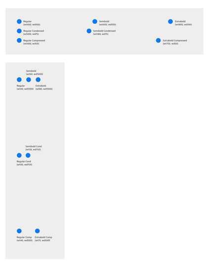
There’s no arguing with sales figures and not-great app support. I do know most fonts that are sold as single styles have variable and interpolating source material. The math certainly has its uses.

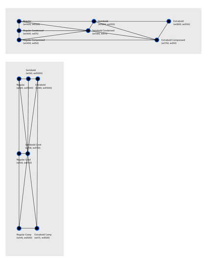
So. Does that mean we can take another look at non-orthogonal non-VF compatible designspaces or is that also too much?

@letterror Looks very interesting! Are the triangles set manually, or are they determined automatically?
@timahrens The edges can be set with Delauney for instance. For 3d spaces that might prevent some headaches. But there can also be value in doing it manually. A 4 master, 2 triangle square has 2 ways of placing them The results at the center will differ from what we’re used to with VF interpolation, but that is ¯\_(ツ)_/¯.

@letterror There is a challenge I have been struggling with for many years, though:

Let’s say the user (i.e. font maker) has a given setup with multiple axes, and then decides to scale everything linearly in one dimension. For example, scaling one axis by factor 10 by adding a zero to the coordinate for all points. They would (rightly) expect that this does not affect the final result.

As far as I can tell, Delauney violates this requirement.

(Don’t shoot the messenger, I am hating this requirement myself but I consider it as inevitable.)

@timahrens The expectations of type designers are shaped by 1992 math that is not more right or wrong than any other. In spatial computing and geo sciences there are so many more different methods of interpolation.

@letterror Not sure what to make of this.

In font interpolation, unlike in geo sciences, the relative scales of most dimensions are arbitrary.

It seems the implications were not clear.

If the scaling of an axis affects the visible result, then, as a font maker, I will play around with different scalings, trying to find the one that gives the best results. For several axes at once. This could be quite tedious.

1/2

@letterror There are some axes which can’t be re-scaled easily, though. For example, the weight axis nowadays is expected to range from 100 to 1000, while the width axis is typically scaled at 50 (compressed) to 100 (regular). This means the width axis has a built-in dominance of roughly 1:10 over the weight axis. Only because someone, a long time ago, decided that 400 is regular and 700 is bold. Had they decided that 40 is regular and 70 is bold then our interpolated fonts would look differently. I am not prepared to accept that.

2/2

@timahrens Ah! You mean how the values are represented in a UI?

@letterror Each master has coordinates, a tuple of values, of course. Same for the interpolated instance(s).

Let’s say in my font project, I have a foo axis that goes from 0 to 100. Then I decide that I want it to go from 0 to 1000 instead. I will simply add a zero to the foo value of each master and each instance. I’d expect that the interpolations remain perfectly identical.

@timahrens @letterror The interpolations should remain identical at the scaled intervals along that axis, but changing the axis scale is also adding or removing intervals, and that unavoidably affects the addressable design space between the axes. That’s already the case in OTvar compatible design spaces, so is the problem significantly different in the kind of non-orthogonal design space Erik is illustrating? Or are you pointng to this as a general problem of multi-axis design spaces?
@TiroTypeworks @letterror It seems surprisingly difficult to explain what I mean. This is not about intervals. What I am talking about is simply scaling the entire setup by a certain factor in one dimension. In other words, multiplying a certain coordinate of each point with the same factor. I believe the requirement for a new interpolation mechanism should be that this must not affect the interpolations. [Edit] As far as I can tell, all the existing mechanisms (VF, MM, Glyphs) fulfil this requirement.
@timahrens @letterror Are you actually ‘scaling’ the axis, though? Unless you are also scaling the outlines, metrics, etc. it seems to me that all you are actually doing is increasing or decreasing the resolution of the axis, i.e. changing the number of addressable intervals on the axis. So if an axis between two otherwise unchanged design locations is 1000 units or 10 units, the axis isn’t any longer or shorter, because its length is determined by the glyphs at either end. The distance between them can be subdivided into more or fewer units, which is determining what is addressable on that axis and in the space between it and other axes (presuming only integers are addressable), but isn’t changing the outline interpolation at relative commonly addressable positions.

@timahrens @letterror So, to go back to your earlier statement regarding the weight axis:

‘Had they decided that 40 is regular and 70 is bold then our interpolated fonts would look differently.’

Would they? We’d still have axis extrema glyph designs that are conceptually and nominally regular and bold. And (user facing value) of 500 or 50 on the different scales would be the same relative distance between those extremes, resulting in the same interpolation result. The only difference between the axes is their resolution. In the one axis the user can address ten times as many integer locations as in the other.

@TiroTypeworks This is true for the one-dimensional case: the results are independent of the axis scale/length/resolution. However, as soon as Delauney triangulation comes into play – or any mechanism that relies on concepts such as Euclidean distance or angles –, we loose this independence. Which means changing the relative scales of the axes may change the result, as different point pairs are considered “close to each other” (as per Pythagoras). At least that’s my understanding.
@TiroTypeworks Oh, with the help of that evil new technology I just found out how all this would elegantly be expressed by a maths pro: “Delaunay triangulation is not affine-invariant”. There you go!

@timahrens

‘as different point pairs are considered “close to each other”‘

Meaning rounding happens differently in any area/volume/banzai* between the axes, yes?

*Yeah, I just used banzai as a generic term for any multidimensional space.

@TiroTypeworks @justvanrossum @letterror Far less impressive than Just’s visualisation, but as I have made it already, here is mine. I didn’t include any triangulation but it’s easy to imagine that there is a risk that an interpolation mechanism, generally speaking, treats the two options very differently even though they are practically the same, only with different axis scales.

@justvanrossum @timahrens @letterror As Erik wrote above re. a 4-master 2-triangle square, there are two ways of placing the triangles, so I’ve been presuming that the triangulation is explicit at the tool level and not automated based on shortest distance.

I am also presuming that axes are normalised, so every two dimensional designspace is actually a square, every three dimensional designspace is actually a cube, and every four dimensional designspace is actually a mindfuck.😁

@TiroTypeworks @justvanrossum @timahrens Well. Such models would not necessarily have to normalize to squares or mindfucks. There is no support for this math in binaries. Spaces can be what the designer needs them to be without any obligations beyond that.