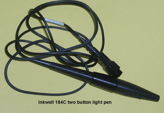
So who knows stuff about the #commodore64 light pen?

Was there an amplification circuit for the light sensor input?

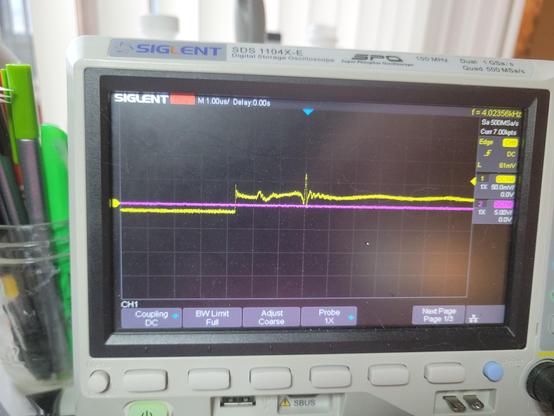
It clearly is responding when I point it up at my task light, but it's barely 30mV. Just no idea if that's what I should be seeing. Also no idea why the 'floor' goes negative...

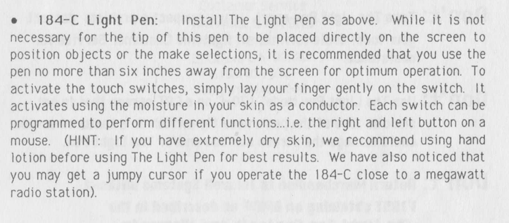
One button is 5V high and properly drops to 0 when pressed as expected. the other button doesn't seem to work, but the CGA only supported one button anyway.

#retrocomputing

@gloriouscow Are you testing it while connected to the C64, or just rigged up to a bench power supply?

I don't know anything about the light pen specifically, except that it connects the light detector to the same pin as the joystick fire button, which is a digital input.

On a joystick that pin is either NC or shorted to 5V (or maybe GND? I can't remember for sure). So I assume there's a pull-down (or pull-up) resistor internal to the C64.

So for a light pen I'd expect one of the following pairs: +5V/NC, GND/NC, or +5V/GND.

I would also hazard a guess that the light pen buttons ought to be connected to pin 3 (Joy A2/Left) and pin 4 (Joy A3/Right) because that's what a paddle's buttons are connected to.

@gloriouscow To clarify, I mean on a joystick that pin is NC normally, and shorted to some other pin when the fire button is pressed. The same is true for the up/down/left/right pins.

@whimsy it's just wired up to my power supply at the moment. I don't actually own a c64 to use it with.

Its not even 100% certain this light pen is for the c64 but I sort of ruled out it being for anything else...

@gloriouscow Got it.

I just double checked and on a joystick the digital pins are shorted to GND when the corresponding switch is enabled. The joystick doesn't actually use the +5V pin at all.

So on a light pen the light detection pin is most likely NC when no light is detected, and shorted to GND when light is detected.

I think taking ambient noise into account that explains the readings you're getting?

@gloriouscow (probably also the second button *does* work, but it uses the same NC/GND setup, and for whatever reason ~5V is leaking into the "working" one when it's NC).

@whimsy Could be. Could probably check that with a weak pull-down?

here was my process-of-elimination chart

@gloriouscow If my understanding is correct you want a pull-up on pins 3, 4 and 6.

AIUI the C64 has a pull-up resistor on pins 1, 2, 3, 4 and 6, so from the programmer's point of view they are active low.

There is a DIY guide to make a light pen for the C64 or Atari computers here: https://www.atariarchives.org/ecp/chapter_6.php

That seems to confirm my understanding, except the DIY light pen has a switch inline with the light sensor.

So it's possible you need to be pressing one of the switches to get any reading from the light pen. Or possibly you have to push the tip hard enough against a surface to activate an internal microswitch.

Electronic Computer Projects - Chapter 6

@whimsy

there's no microswitch, and i did try fussing with the buttons while holding it up to the light.

if it helps, this appears to be the pen i have, an "Inkwell 184C"

Hardware Requirements - InkWell Systems The LightPen Manual [Page 10]

InkWell Systems The LightPen Manual Online: Hardware Requirements. The Light Pen is joystick Port I compatible with Commodore 64, 64C, SX64, and 128 computers. To program for The Light Pen you will need: • A COMPUTER WITH SUITABLE LIGHT PEN INTERFACE • COMPATIBLE DISK DRIVE • TV OR...

ManualsLib
The Light Pen Operations Manual Inkwell Systems : Free Download, Borrow, and Streaming : Internet Archive

Light Pen by Inkwell Systems and it comes with a demo disk! Enjoy!

Internet Archive

@whimsy

you know in my entire life of using computers and reading manuals, I have never before been advised to moisturize myself

@whimsy the capacitive buttons were a bad call. you really miss the tactile feedback of a switch. it feels crummy to not be able to just rest your finger on it either
@gloriouscow yeah that's awful 😕. It wouldn't even have occurred to me that someone would make such a thing in the 80s.

@gloriouscow So FWIW I've confirmed the C64 does indeed have pull-up resistors on the digital pins of the joystick ports (pins 1, 2, 3, 4 and 6).

To be more specific, the MOS 6526 CIA has internal pull-ups on its IO pins, and the digital joystick pins are connected directly to IO pins on the CIA.

(https://web.archive.org/web/20181126000922if_/http://archive.6502.org/datasheets/mos_6526_cia_recreated.pdf page 5)

The analog pins (5 and 9, not used by light pen) are connected to the SID!

@whimsy Thanks, this is helpful. I checked the CGA schematics, and they expect an active low strobe and button/switch input, but the card itself has no pullups, so there were clearly platform implementation differences to account for.
@whimsy They also send both +5 and +12V up the light pen header. I wonder if there were many 12V light pens...

@whimsy

you'd never see anything like this in a consumer product today.

"You can use our product with other computers but you'll probably have to cut the end of it off and do other stuff. Hope you know what you're doing."

It was a different era.

@gloriouscow Yeah, I saw that too!
I have a few old computers and peripherals whose manuals have pinouts for all the ports in the back. I miss that.