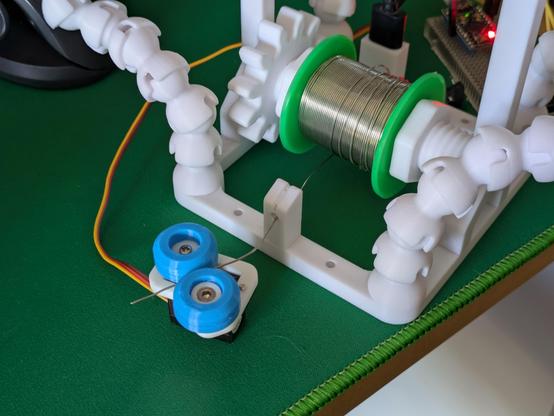
Proof of concept: A servo motor, a little platform with an opposing wheel, and two TPU tyres with a tiny groove down the middle will very capably grab a length of solder and push/pull it.

This is part 1 of the next addition to my soldering station: a pen that precisely pays out solder wire as it's needed.

I have some continuous rotation servos and some 1mm ID PTFE tubing in the mail. This should be a quick, fruitful project. #3DPrinting #Arduino #maker #SolderingStation

Using the same principle as a bowden tube on a 3D printer, I can easily push 0.8mm solder through a PTFE tube with an inner diameter of 1mm. This is super flexible and movable and should flawlessly transport solder from the reel to the solder pen at the other end of the tube.
And a first go at lining up the tube with the rollers on the platform to help me think about the best way to do that bit. I won't go any further on this iteration since the continuous servos are actually due to arrive today and I expect them to have slightly different proportions so I will need to remake the whole platform soon anyway.

Tiny robot makes a whining sound and smoothly extrudes a length of solder wire (and then falls over because it doesn't have enough weight to pull on the spool and just pulls itself over instead).

That I think is the proof-of-concept for the base done - there are tweaks to make and some more electronics to stuff inside but those are details.

Should I design a little cover to snap/screw on top of this or should the wheels stay visible like this?

Continuous rotation servo + a 608 size bearing and TPU wheels + PTFE tubing + fewer 3D printed parts than you'd think + actually securing this contraption to my soldering station = a computer-controlled power feed for solder wire, for those long electronics assembly sessions.

Even before starting on the second part (the actual pen with buttons you hold at the other end of the tube) this is a serious project milestone and I'm very happy with it. #maker #3DPrinting #SolderingStation

A first pass at the shape of the solder pen itself. A 1.25mm diameter pipe through the body of the pen allows for the PTFE tube to be threaded in easily.

A cutout for a very slim PCB with two tactile buttons and a 3-pin header will also run through most of the pen - currently the buttons are just solid to get a feel for it in the hand.

Behold: the prototype solder feeder pen, and the parts it's made up of. The grey bit is a facsimile of the circuit board I've designed to slot in here - it just routes two tactile buttons to a three pin socket (one to each button with a pullup resistor in the microcontroller, and a common ground).

The thinnest PCB that JLC will sell me without charging me more is 0.8mm, so there's a 1mm clearance in the print for it to slot in securely.

Time to order some electronics!

Printed another simulacra, this time of what I think the mainboard in my solder feeder will look like, and test-fitted it in an experimental base.

I need to squish a Pro Micro clone, two tactile buttons, a connector for the pen electronics and another one internally for the servo into one half of the base (the other half is mostly servo body) - I'm pretty happy with how this prototype slots and locks in.

Have now designed and ordered the main PCB for my solder feeder. It's entirely unlabeled because my SVG outline didn't appear for some reason but that won't stop this prototype from happening.

This PCB layout looks chaotic as hell, but it'll make sense once stuff's been soldered to it - it's double-sided and has to situate stuff in precise places in a very small box.

For my own benefit in a couple of weeks: Pen buttons are pins 2/3, main buttons are pins 4/5, servo is on pin 6.

I appear to have ordered some PCBs exactly at Chinese new year. I absolutely cannot begrudge them that so I guess this project gets shelved for a while longer than planned.
Both sets of PCBs for this project are now in the mail. Might have to remember not to have any bright project ideas in February in future to avoid getting stymied by the Spring Festival.

Success! Very small PCBs have arrived.

The long ones are 0.8mm thick - I think I could snap one if I wanted, but it's not going to happen by accident.

Also there are five of each and I bought plenty of everything else, so if anyone else in Australia thinks they might like a solder feeder pen, sing out.

That moment you realise, just as the solder is cooling down on the very last component, that you made a mistake weeks ago and put the pad for a component on the wrong side of the board and prototype #1 is garbage without rework

Not my best, not my worst - but for a V1.000 of something that is unreasonably crammed into as tiny a space as I could imagine, it's come together pretty well.

This is the mainboard for my solder feeder - the 3-pin socket near the Pro Micro's USB port is the connection out to the pen itself, the 3 pins at the back end go to the continuous rotation servo that actually moves stuff, and there are four buttons - the two on the main body will be for fast feeding, the two on the pen for slow.

Well, the electronics seem to work correctly - all four buttons can make the servo run back and forth - but now there is a new problem: the servo suddenly looks and sounds underpowered, moving much more slowly than it did when everything was on the breadboard.

No code changes, and the extra electronics are just input-pullup buttons. Not sure why it'd behave differently now. A new spare servo acts exactly the same, and it's the same whether powered from VCC or RAW.

Now witness the power of this fully armed and operational solder feeder!

The power issue I think came down to a crappy Pro Micro clone board - another successfully flashed once and then permanently died, so the one in this short clip is actually the third one I've tried. It also sometimes cuts out until it's power cycled - I think it's overloading a cheap 5V regulator, version 2 will be powered from RAW rather than VCC.

This Works. Time to finish the enclosure. #3DPrinting #Electronics

The code for this thing is dead simple - it reads from four buttons, then an if-then-else tree says what the servo does.

A regular servo gets commanded to positions expressed in degrees - 0 is fully one way, 90 centred, 180 fully the other. A continuous rotation servo like this one takes the same commands, but those values become relative speeds - so zero and 180 are full speed one way or the other, and 98 and 85 are the closest values I could get working for the slow feed option. #Arduino

My completely arbitrary obsession with stuffing the entire workings of this thing into an equally arbitrary 4x4x4cm cube because that's how big a square I drew in Rhino 3D on day one of this project is... resulting in a pretty nice little clockwork-looking object.

I'm not loving the "Iron Grey Metallic PLA Metal" filament as much as I would for this though, that might be prettier for more monolithic parts but I think I want something more matte for this project in the end. #3DPrinting

Holy crap I got the entire servo's cable in there - and it's powered up and spins when I press the buttons.

It spins the *wrong way*, but that's okay - that USB socket there is the Pro Micro so it's very easily reprogrammable. #Arduino

The fully assembled solder feeder, now attached to the front of my #SolderingStation. It replaces the simple little stand I previously used to just bend the end of my solder wire over - that's still attached next to it in case I ever want it again.

I think the trick with this filament is to print with super low layer height, and enable ironing - the top of this thing looks like machined delrin or something.

Last step is finishing the feeder pen itself.

This is a failed print (the other half of the pen lost bed adhesion and became plastic spaghetti), but enough of it worked to confirm I now have the negative space cutout for the feeder pen's electronics correct enough to spend time refining the outside shape.

It started with a roughly cylindrical cross-section, but that immediately made it tougher to print - and it already is a technical print because of the thin walls and large hollows everywhere. Pen v2 will have a simpler form. #3DPrinting

Went for the smarter option of "look at the internals, then design an enclosure around them" rather than "try and stuff everything into an arbitrary tiny shape" and ended up with this extremely functional part. Still need to make the button insert, but this thing absolutely works - press the button, more solder wire appears.

Could I actually be close to - dramatic gasp - finishing a project!? Better yet, as an infrastructure project, this'll make it easier to finish *other* projects as well.

I am now extremely bored of making sub-millimetre adjustments to this tiny button part, but I am pleased to report: it works! Press the button, solder comes out; press the other button, solder goes back in.

The tube is held rigidly and almost completely straight - there is one bend near the nozzle because it has to be off-centre to run underneath the PCB, but I think that might actually help to keep it straight as it deploys.

The solder feeder pen has reached v1.0. #3DPrinting #Arduino #maker

Hocus pocus, abracadear; I would very much like the sponge that came with my soldering iron to re-appear

I guess this is a sign it's another thing I should make myself and attach to my soldering station?

I usually try not to toot my own horn too much, but I will do so when I'm proud of making something good - and my solder feeder fucking slaps.

This is the first real test done in anger, and there are definite changes to make. It needs a narrower nozzle to get closer to the workpiece, a longer one to straighten the wire better, and a more comfortable handle.

But I will never go back to just feeding solder in by hand. This is 1000% better in every way.

#3DPrinting #Electronics #Arduino #maker

Thinking about what modifications might be needed in order to hand one of these to someone else to use. And what would need to change to suit different sizes of solder - mine is 0.8mm, but I've heard 0.5, 0.7 and 1.0 are common.

The 3D printed tube anchors could be simplified to work with multiple sizes, and the TPU wheels probably don't even need a groove when the wire is guided by tubing - so maybe the only things that needs to swap for different sizes are the PTFE tubing and the pen.

From day one, I designed the thing to screw to the base of my own #SolderingStation project, which includes a spindle for a roll of solder. I could make a basic version of that to go with the feeder.

It's not hard to hook a roll of solder onto something, but the feeder will work best when it's pulling right off the top of a roll, so a bespoke 3D printed part to put things in the right position won't be much of a chore.

There's also been questions about speed control. I didn't get quite the range of adjustment I was expecting out of a continuous rotation servo - the "full" speed is maybe 1.5-2x what the pen buttons do currently - but maybe there's a beefier servo option, or scope for a more traditionally motorised version.

The wheels being as big as they are also have the effect of gearing the mechanism up, and I based their size around the bearing I had sitting in a drawer, so that could be adjusted too.

I removed the notch from the wheel model, found a really good profile for printing TPU that I've used before, and cranked the layer height down to 0.08mm for these new wheels - new ones on the left, old ones on the right.

Those are gorgeous prints, given they are only 1cm tall and 2cm across.

The notch isn't necessary because the wheels just provide linear motion in one direction or the other -keeping the wire aligned is the job of the PTFE tubing either side. #3DPrinting

This test print nozzle is firmly in the category of "things I didn't expect to go well". This is super thin - the top 10mm or so has a 3mm outside diameter, with a 1mm channel running through it - and it was printed upright, at 0.08mm layer height. It's surprisingly strong... but even if it broke, this would be trivial to re-make.

It's been hand-drilled out to 1mm, which is still very sloppy for my 0.8mm solder wire - guess I need to buy a set of very small drill bits. #3DPrinting

For print reliability reasons, I would probably print these nozzles in a flat orientation - that would make them significantly stronger (and easier to make much longer for better access to joints on crowded boards). This test though worked way better than expected.

Part of what I'm calling power issue might actually be a traction issue - since removing the notch from the wheel design, I'm noticing the idler wheel sometimes doesn't turn when the mechanism is moving, and the solder wire is slipping as a result.

A simple fix there might be to gear the two wheels together, forcing both to turn mechanically - currently the idler is just driven by friction with the servo's wheel. That won't be too difficult to introduce I don't think.

Okay, this might be the coolest thing I've ever designed and printed. The wheels for my solder feeder are now geared, so one will drive the other, while retaining the flat zone (outsized by 0.1mm so it's the main contact point between the two wheels) in the middle for gripping and pushing the solder.

This is printed in TPU using this profile, at 0.08mm layer height: https://www.printables.com/model/552337-p1p-tpu-profile-configurations-black-overture-tpu

Will this actually work? Time will tell, now I have to rebuild the feeder base to fit these. #3DPrinting

It works - the new tyres introduce so much grip that they have zero slip with the solder wire and can push it back and forth all day, no worries at all.

The new tyres have, however, introduced a new issue - there's now so much power and resistance in the mechanism that the wheel rim attached to the servo is *unscrewing itself* after a few turns.

Fortunately I foresaw this forever ago and added a hole for a tiny grub screw to press up against the servo's splines! That's been there since v1 of that part. Problem solved, I think. #3DPrinting

That might be it for now, until the new servo arrives or I want to change something about the pen. Here's my current #SolderingStation setup, the solder feeder mounts to the front and the spring clips hold my Pinecil and the feeder pen when not in use so the whole thing packs up vertically and is carry-able with that handle.

I didn't actually need to put headers on this Pi Pico for any particular project, but - I'm sure you'll understand - I needed to solder *something*.

#3DPrinting

With apologies to the Whitlams:
🎶 Chunky chunky servo motor now
🎵 Chunky chunky servo motor

Some specs I found on the big one suggest it should be able to rotate about once per second under full power. With 2cm diameter drive wheels, that's about 6 centimetres of solder wire delivered into a workpiece every second - does that sound like enough for your purposes @jpm ?

@timixretroplays lol hopefully! I can send you some 0.5mm, 0.8mm, and 1.0mm solder to test with if you like
@jpm that would be wonderful actually - I can find small tubes of 0.8 and 1.0 at Jaycar, but nobody seems to want to bother selling me less than 100g of 0.5 and I definitely don't need that much of it
@timixretroplays Can you run the PTFE tube through the nozzle? Or this would make it too thick?

@Siff so the goal of the nozzle idea here is two-fold - put the very end of the pen as close as possible to the workpiece, being as narrow as possible to avoid interference, and also to provide the narrowest possible tube for the solder to pass through, for as long as possible, to straighten it.

I'm going to switch to a larger PTFE tube to carry any width of solder wire - the pen nozzle will be interchangeable and be slightly larger than the wire in order to constrain it straight.

@Siff the PTFE is already a few fractional millimetres wider than the solder wire, and it moves about in there and often comes out slightly curved. The current pen does run the PTFE tube right to the nozzle, and that creates this issue. I want a design that works irrespective of the tube's diameter but can be adapted easily for any width of solder.
@timixretroplays Ok, I understand. On the pictures it looked that the PTFE tube is a better fit, but apparently that’s not the case.
@timixretroplays
An N20 motor with encoder would give you choice of gearbox, and allow you to do speed control in software
A luer-lock (blunt) syringe tip on the pen would be plenty rigid and make the pointy end cheap to replace and suit any size of solder

@BrettRD that motor looks like it would do the job, but it'd mean adding a motor driver to the project - I want to try keeping to a servo if I possibly can for simplicity.

I have a couple of "DS3115-360" servos on their way, I figure a more powerful servo will give me more options for speed as well.

I'll see what I can get away with for 3D printing the nozzle, if I have to resort to an off-the-shelf part for that I will.

@timixretroplays thinking out loud here so take or leave as you like, maybe spring-load the idler wheel, and the idler and drive wheels are a pair of convex/concave with the same radius. Bowden tube diameter from the drive to the pen shouldn’t matter too much with any diameter solder, but the tip will probably need to be changed out for different diameter solders otherwise the solder will move around too much in the tip

@jpm hmm, you're very right about that - the only critical dimension is where the solder exits the pen, and maybe that's manageable with 3D printed nozzles for different sizes - mating the end of the tube to the base of the nozzle is a concern but I have some ideas to try out.

I don't love the slop/backlash caused by having a bigger tube ID than the thing it's carrying, but that's not really an issue for this application.

@timixretroplays wasn’t there a really long thin tapered nozzle that some 3D printer folks started getting excited about a few years ago? I’d be worried about the nozzle getting too hot next to the soldering iron, so a replaceable metal nozzle might be better
@jpm not sure what nozzle that would be, I'm not up on the cutting-edge 3D printing meta, but there's ways to mitigate that. PLA like I've been using will absolutely melt and stick to a soldering iron in a split second, but I could go to the other extreme and print the nozzle from polycarbonate which gets printed at close to 300 degrees.
@timixretroplays airbrush nozzles! I wonder if they go up to like the 1.2mm range? But even 3D printer nozzles might work pretty well, especially longer tapered nozzles like Mk8
@timixretroplays This is really neat! Currently I am not soldering that much, but this is soooo convenient looking! Nice one!
@timixretroplays what diameter solder have you tested with? On my desk right now I've got 0.5mm SAC305, 0.8mm SnCu07, and 1.0mm SnPb 60/40. Is the feed speed adjustable?

@jpm mine is 0.8mm, and that tube is 1mm ID PTFE. I guess it could work with any diameter but you'd want a thicker tube for 1mm solder. The wheels might work for 0.5mm but every part is redesignable and replaceable.

The speed is kind of adjustable, it's a continuous rotation servo not a stepper so power is a bit limited and in the video it's about as slow as I could get it to go without choking. Tell me about your speed use case? A future version with a stepper is very doable.

@timixretroplays the speed is related to the diameter of the solder - smaller diameter solder needs higher speed for the same volume of solder in the same time. Target time for a normal'ish PTH joint (e.g. a 2.54mm pitch pin header) is 3-5 seconds so you don't overheat the component, and you have to feed the 0.5mm diameter SAC305 solder pretty quickly to get enough solder into the joint in that time.
@jpm oh, it does go faster - the buttons on the main unit spin the servo as fast as it can go, my idea for that being you'd use those buttons to feed a new roll of solder into it and then the buttons on the pen are slower. The brain in there is just an Arduino Pro Micro and the code is dead simple so you could make the pen buttons full speed as well in no time at all.
@timixretroplays if you don't mind An Suggestion, something like press both buttons on the remote at the same time, the press feed to increase speed or reverse to lower speed, then both buttons again to set?
@timixretroplays
That look really awesome! Are you planning to write about it or even give instructions how to reproduce this? It looks really useful!
@mwick83 I'll be doing some sort of writeup about it, likely offering models to download and possibly also selling assembled units. We'll see - there's a bit of work left to do before it's in a state to present to another person to use.
@timixretroplays hmm, maybe I should adjust mine with a pen too...
@timixretroplays I want to make one of those so bad! Will you be posting instructions and models and/or selling the PCBs?

@Lynx I definitely want to share instructions and models. I would consider selling kits or assembled units but there's a bit of work to do before that could happen.

There's 3D printing, electronics assembly and Arduino programming involved in building one, so choosing to make kits means assuming people will have the means and ways of doing one or two of the others in that triangle. I think if anything I'd be inclined to sell a ready-to-go unit with some kind of spindle for a spool of solder.

@timixretroplays That makes sense. Personally, I have a 3D printer and I'm fine doing Arduino programming; the only things I can't easily do at home are PCB manufacturing and SMD soldering, so I'm personally mostly just interested in PCBs. Though if it's something I can put on perfboard, I can do that.

Elecrow actually has a sort of drop shipping thing where you can upload your design, and then other people can order it and you get a cut. I don't remember all the terms at the moment, though.

@Lynx I design my PCBs in Fritzing (basically the Fisher Price My First PCB Design Program, it's close to drag-and-drop) and order them from JLCPCB - the day I figured out I could make my own little breakouts and things and have them show up a week or two later was a game-changer.

I very specifically avoid SMD anything, anyone saying "go on, it's easy" is looking at it from the wrong side of the accessibility fence and if I can't do a PTH version of something I won't do it.

@timixretroplays That's a great approach! Means all I'd need is PCBs, or just design files so I can order some 😸
@timixretroplays @GamesMissed Nice. I made a manual version a while back, and hadn’t seen any new innovations since then until yours. https://araxia.net/keyboards/solder-feeder/
araxia.net - Bespoke Handheld Solder Feeder