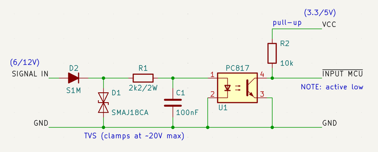
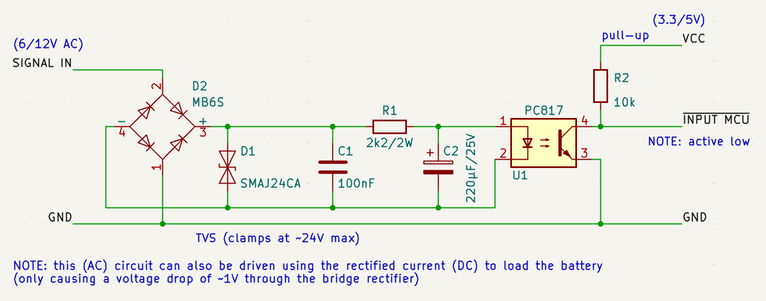
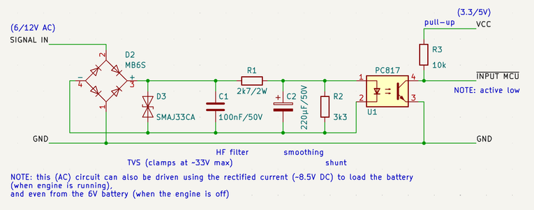
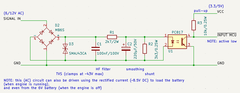
Have been working on the input and output connections of the digital cockpit for the classic Honda MT mopeds. Isolating everything properly using optocouplers and MOSFETS takes quite some real estate. Now I understand why the control units for cars are so packed.

The good thing is that I can replace each set of four PC817 optocouplers with a 4-channel TLP291-4 optocoupler, and the pull-up resistors with resistor networks.

#DigitalCockpit #electronics #HondaMT #bikelife

Turns out that some of the lights -- old-school filament light bulbs -- are fed directly from a separate spool circuit on the stator, which means that alternating current (AC) is used there. So in order to light up the right indicator lights in the cockpit, each raw input from these lights will have to have its own rectifier block, TVS clamping diode and smoothing capacitor before it can be fed into the optocoupler.

#DigitalCockpit #electronics #HondaMT #bikelife

@OffermanIndustries You can't have a common ground between the AC input and the DC output with a bridge rectifier.

The diode between connections 2 and 4 of the bridge rectifier will short out the negative-going half cycles of the input signal.

There should be a separate connection for pin 4 of D2, the negatives of D1, C1, C2 and pin 2 of U1, and that mustn't be connected to ground.

Pin 1 of D2 and PIn 3 of U1 can be connected together.

@diver300

Got it: isolated the DC ground wire from the rectifier up to the optocoupler per your description.

Thank you for pointing this out! saving prototype PCBs 😅

#DigitalCockpit #electronics #HondaMT #bikelife

@OffermanIndustries
Glad to help. I think what you've drawn will work.

I would put a resistor in series with the input. If a bulb blows, the open circuit voltage of the generator can be big, and you will get a lot of heat in D1.

You don't need much current at all to turn on the LED in U1, so your circuit would work fine with quite a lot of resistance in series.

I would also add some resistance in parallel with the LED in U1 so that stray current of a a few microamps can't turn on U1

@diver300

Yes, that is a real-world problem: when one of the bulbs powered by the AC feed blows, the missing load causes a cascade of failures. The rest of the bulbs blow too, and then the diode for the battery loading circuit (fed from a different wire from the same spool) gets too hot, can even melt. That's why even during normal operation, the AC circuit is connected to a 1r3/30W resistor mounted on the frame when the lights are switched off.

@diver300

The total resistance is quite the balancing act here. I hope to get this circuit working for both 6V and 12V electrical systems, and too much resistance results in the optocoupler no longer switching.

My reasoning: 6V AC RMS -> 8.5V peak, minus 2 times 1V drop over the rectifier, and 1.2V drop over the optocoupler's diode, leaves 5.3V.
So to get a current of 5mA, the total resistance can be no more than 1k.

So I now switched to an 820r resistor and beefed up the other components.

@OffermanIndustries Also, the current transfer ratio of the PC817 could be as large as 600%. With a 3 V supply, making the MCU input low could take as little as 0.2 mA, so about 30 uA in the LED.

I just don't think it's a good idea to have circuits that can be triggered by 30 uA. If you put 2 kOhms in parallel with the photodiode, you know it won't be trigged until there is about about 0.5 mA.

@diver300

Worked your suggestions into the schema, be it with slightly lower values for the resistors, so this input circuit will also work for 6V DC from the battery (when the engine is off).

Calculating minimum I_F for DPC817:
I_C for 3.3V = ~0.3mA.
For I_F = 1.0mA, CTR = 0.45 -> I_F = 0.45mA.
With a voltage drop of 2V for the rectifier and V_F = 1.1V at 1mA for the optocoupler, max R = 2900 Ohm.
Hence the 2k7 resistor.

I'm gonna give this a try 👍
Thanks again!

@OffermanIndustries I still think that D3 isn't needed, and will just burn out if the bulbs fail.

@diver300

You may be right: I know for a fact that back in the days some people with completely messed-up wiring ran 24V bulbs on a 6V system to prevent them from blowing. Besides, these clamps are only meant to handle short spikes.

What I did for now is beef up D1 to 100V and replace D1 with a SMAJ43CA. C2 at 50V will be sufficiently protected by R1.

@diver300

I'm gonna measure the raw AC power that is coming from the spool and test how this circuit is holding up. Since D1 is in parallel, it can easily be replaced/removed/left out from the board.

Thank you! (will post my lessons learned here 😅)