Less-recent self: "I can skip the resistors for the LEDs, right? They're salvaged, they'll be blinking on and off anyway, and I only have them on here in the first place because these jacks can't fit in 2hp and I didn't like having all that unused space when I went to 4hp. Plus it'll be interesting to see how it works out, right? Yes. I will leave them off For Science! "
More-recent self: "Why did I wire these up like this? This is Wrong and Embarrassing. I must correct this IMMEDIATELY."
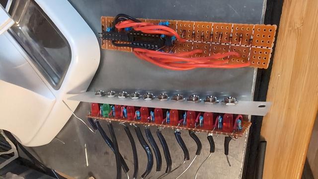
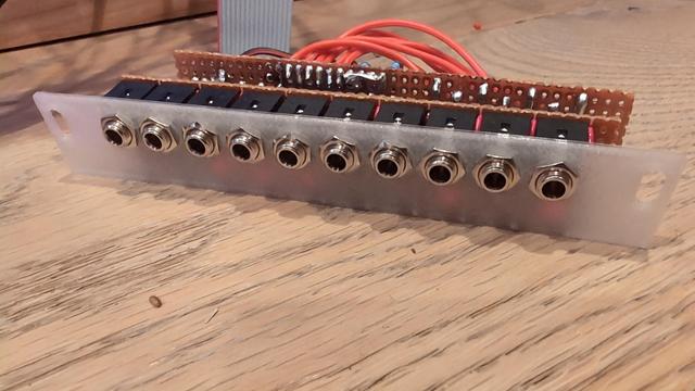
No epoxy yet because I don't have proper PPE for that shit at the moment, and won't until December 3rd at the earliest. Still gonna wire it all up and test it out a bit. Here's a progress photo.
Hope I don't fry anything!
I've figured out the problem and I'm not sure how this design made it off the breadboard. I thought it was working poorly because of loose connections; it was working *at all* because of loose connections!
There's enough room left on the perfboard to correct my mistakes, I think.
Well. I modified the perfboard prototype, but still no luck.
Problem had been that the serial clock needed to be the inverse of the register clock for my serial-in, parallel-out shift register to behave like a serial-in, serial-out register. Breadboard prototype had been unstable enough that it kinda worked with them just tied together.
Fails differently now, but still fails. Back to the multimeter.
Huh. There is a short between pins 10 and 11, but only when there is a power cable plugged in.
It does not matter if the power cable is plugged into anything on the other end.
This is a mechanical problem.
Maybe I'll set this project aside for a bit. My workspace is a disaster and the housework's getting neglected again. I should make an actual schematic in the meantime. Most likely I'm going to have to discard the current perfboard mess. I don't have high hopes regarding my ability to salvage something workable from this at the moment.
Probably time to get some sleep, too.
Right. Using PCBs seems to be popular. I'm not an electrical engineer by training. Here's the schematic I've come up with. Anyone feel like taking a peek?
http://lyk.so/eurorack/shift-register/schematic.pdf
Gonna start designing a board with this schematic and see where that lands me.
In the meantime I've set up a website where I might, in the future, sell a couple copies of my modules to defray my parts and fabrication costs, provided I can come up with something that seems sound enough.
Continuing to work on the circuit design. I think, once again, I've arrived at something that works which also addresses the previous design's deficiencies. I am using an op amp for the first time, because buffered outputs are important!
Still unsure of whether to use 8V or 5V gates, but leaning toward 5V just to keep things simple. If it's good enough for ALM, it's good enough for me, right?
Considering learning to hand-solder surface mount parts in order to make designing the new PCB easier.
This browser-based circuit simulator has been very helpful for testing out basic concepts. Transistors and op amps are still shaky territory for me, it seems.
New schematic dropped. Old schematic had really obvious, embarrassing errors. New schematic (probably) has less obvious, less embarrassing errors!
http://lyk.so/eurorack/shift-register/schematic.pdf
I would be shocked if it has *no* errors, but I'd be okay with being shocked in this particular case. 😸
I now have 9 bypass capacitors on this board. I think this may be overkill, but I'm erring on the side of overbuilding because I really kinda don't know what I'm doing yet.
3 for +12V, 3 for -12V, and 3 for 5V.
Success! The third approach is significantly better. Going to proceed with iterating on it. The biggest issue with the previous two had been the strength of the tip connection. Now the biggest issue seems to be how much the wire tends to shift in the channels. This doesn't seem to be an issue for *basic* function, but I decided to also add jack sensing to the third design; that now seems to be the weak point.
Also, allowing the mechanical stress to transfer to the solder joints seems bad.
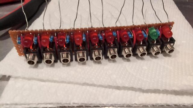
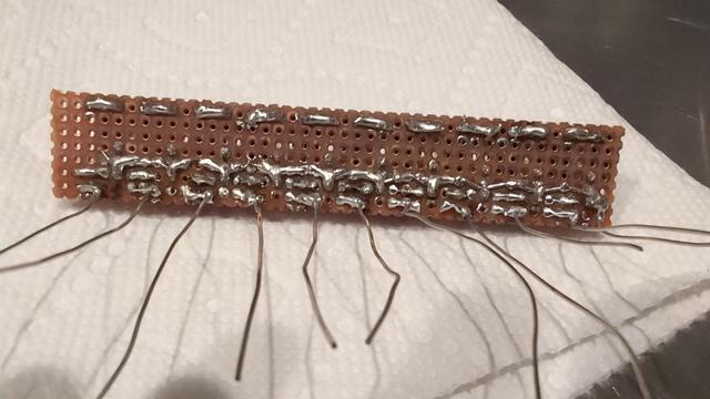
Looks like y'all are somewhat interested in what I'm doing here, so here's a photo of some of my attempts.
The two big rows in front were my first, as I plan on making this an LED and jack assembly and foolishly though this would be simple. The one on the perfboard had severe pin mobility problems and was not very forgiving of imprecise wire work. It did at least allow me to confirm my ability to solder a pin connected to PLA without melting it, though.
More details in the alt text.
Pondered a little, considered twisting the wire on top and/or bottom and leaving a cutout to tuck the twists away, buuut... that seems fiddly and bulky.
I constructed the pin channels in the second row assembly from two cylindrical cutouts bent about 10 degrees away from each other. My intent had been to make a somewhat springy arch inside the jack sleeve, but it seemed to keep the wire in place pretty well too... 🤔
That helped. Not enough, but it did help. If it were soldered in place, it wouldn't move, but it'd be better if it didn't move without the solder as well.
Might try a more extreme angle next. 20 degrees was *too* extreme the last time I tried this approach. Either the correct angle is between 10 degrees and 20 degrees, or I need a fundamentally different approach.
Heading in two different directions now. One involves printing an insert for my 22 AWG solid core wire to wrap around. The other involves buying a bit of tinned copper ribbon, like the kind used to make battery packs, and using that as the leads on one side instead of wire. The latter seems more robust but less accessible.
I'm going to continue developing the former approach until the tinned copper ribbon arrives. I suspect the latter will be more robust.
This design will require bigger through-holes than I'd wanted. Little room for bosses here. But the tip insertion sensing is working reliably so far, at least with this one prototype. The sleeve insertion sensing pin seems to be getting pushed too far up to return to the right position, so I'll have to try adjusting that.
Uses two paperclips per jack.