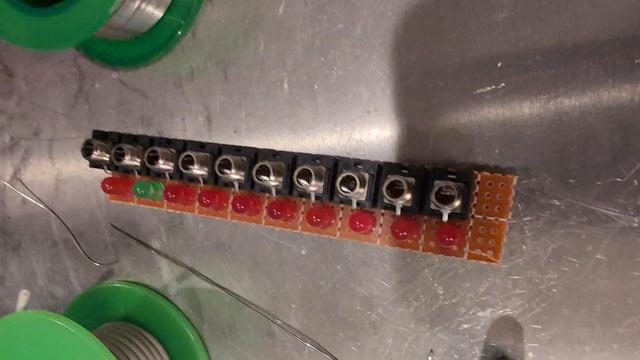
Less-recent self: "I can skip the resistors for the LEDs, right? They're salvaged, they'll be blinking on and off anyway, and I only have them on here in the first place because these jacks can't fit in 2hp and I didn't like having all that unused space when I went to 4hp. Plus it'll be interesting to see how it works out, right? Yes. I will leave them off For Science! "
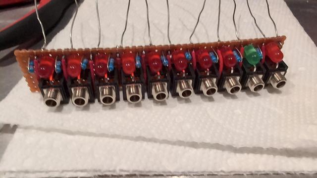
More-recent self: "Why did I wire these up like this? This is Wrong and Embarrassing. I must correct this IMMEDIATELY."
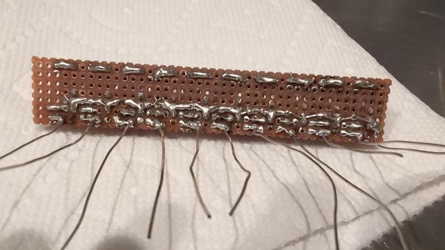
I've figured out the problem and I'm not sure how this design made it off the breadboard. I thought it was working poorly because of loose connections; it was working *at all* because of loose connections!
There's enough room left on the perfboard to correct my mistakes, I think.
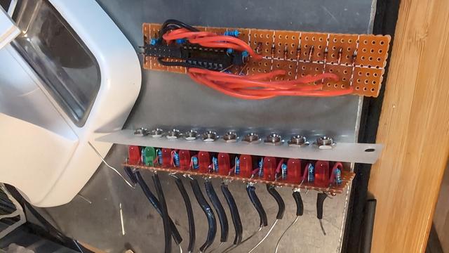
Well. I modified the perfboard prototype, but still no luck.
Problem had been that the serial clock needed to be the inverse of the register clock for my serial-in, parallel-out shift register to behave like a serial-in, serial-out register. Breadboard prototype had been unstable enough that it kinda worked with them just tied together.
Fails differently now, but still fails. Back to the multimeter.
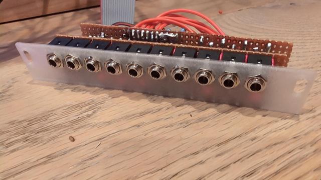
Huh. There is a short between pins 10 and 11, but only when there is a power cable plugged in.
It does not matter if the power cable is plugged into anything on the other end.
This is a mechanical problem.
Maybe I'll set this project aside for a bit. My workspace is a disaster and the housework's getting neglected again. I should make an actual schematic in the meantime. Most likely I'm going to have to discard the current perfboard mess. I don't have high hopes regarding my ability to salvage something workable from this at the moment.
Probably time to get some sleep, too.
Right. Using PCBs seems to be popular. I'm not an electrical engineer by training. Here's the schematic I've come up with. Anyone feel like taking a peek?
http://lyk.so/eurorack/shift-register/schematic.pdf
Gonna start designing a board with this schematic and see where that lands me.
In the meantime I've set up a website where I might, in the future, sell a couple copies of my modules to defray my parts and fabrication costs, provided I can come up with something that seems sound enough.
Continuing to work on the circuit design. I think, once again, I've arrived at something that works which also addresses the previous design's deficiencies. I am using an op amp for the first time, because buffered outputs are important!
Still unsure of whether to use 8V or 5V gates, but leaning toward 5V just to keep things simple. If it's good enough for ALM, it's good enough for me, right?
Considering learning to hand-solder surface mount parts in order to make designing the new PCB easier.
This browser-based circuit simulator has been very helpful for testing out basic concepts. Transistors and op amps are still shaky territory for me, it seems.
New schematic dropped. Old schematic had really obvious, embarrassing errors. New schematic (probably) has less obvious, less embarrassing errors!
http://lyk.so/eurorack/shift-register/schematic.pdf
I would be shocked if it has *no* errors, but I'd be okay with being shocked in this particular case. 😸
I now have 9 bypass capacitors on this board. I think this may be overkill, but I'm erring on the side of overbuilding because I really kinda don't know what I'm doing yet.
3 for +12V, 3 for -12V, and 3 for 5V.