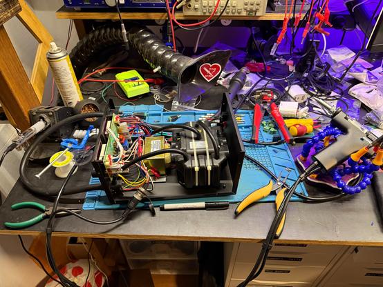
I’m most of the way to retrofitting my soldering & hot-air station to be a *de*soldering & hot-air station instead. I’ve added the new connector to fit the desoldering gun and wired up the trigger for the vacuum.
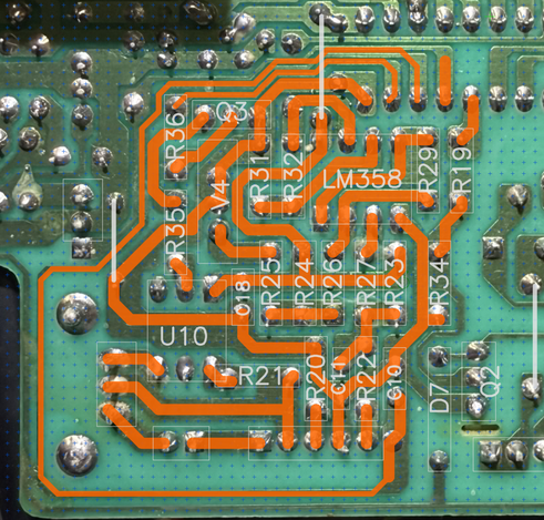
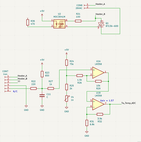
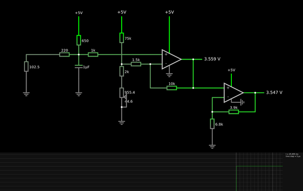
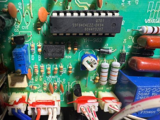
Only trouble is the thermistor is different to the type in the original iron (which I can’t find, but the internet suggests is a K type thermocouple?). Hopefully I can work out what type this is and bodge the op-amp circuit to calibrate it into useful range.

#s0Projects #tinkering

Progress! Reverse engineered the analogue section with PCB photos, KiCad and Horizon EDA, then simulating with Falstad Circuit JS... but I haven't worked out what's wrong here yet, I'm not seeing any movement coming out of the first opamp in the sim.

Possibly I've read one of the values wrong, or missed a component entirely? Any suggestions?

@s0 assuming 200m or so on the left side of R26, the output of U1A should be approx. 10x the voltage on cap C11 - 2V or something, the LM358 cannot swing to the positive rail, so in your example it's just clipped to the max. positive output. That makes sense. ([1], Fig 5-11)

What's supposed to be within the tip? If it's really a K-type thermocouple, you'd expect something like 10 millivolts at 300°C... [2]

[1] https://www.ti.com/lit/ds/symlink/lm358.pdf
[2] https://www.omega.co.uk/temperature/pdf/Type_K_Thermocouple_Reference_Table.pdf

@vogelchr in this case I’m trying to match the behaviour I was able to observe for whatever was in the original iron — I used a resistor decade to test it from 60-200 ohms to produce the full temperature range and measured 0-1.5V on the output of U1B accordingly. Let me post my measurements