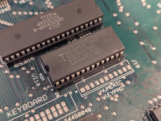
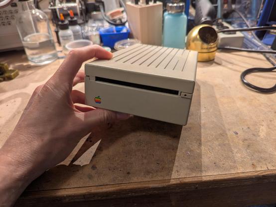
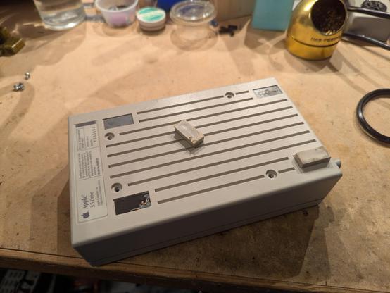
I got a new computer!
looks like a ROM 0.
there's some surface rust to clean up.
these RIFA capacitors will need to come out. they're just waiting to go up in smoke at this point.
many of the electrolytics have also gone bad.
ooh yeah the RIFA caps were on the verge of failure
need to fix up some Apple 3.5 drives.
the feet come off easily on these drives. maybe I'll try printing replacements with TPU.
something's not right! actually it's very common for stuff from ewaste to be missing any captive cables. those get cut off for copper scrap and to prevent items from tangling. engineers: please don't design products with captive cables!
this'll need cleaning and lubrication. probably also a new eject gear.
yeah that gear is basically a nilla wafer at this point
good thing you can just 3D print a replacement gear.
going back to the IIgs enclosure, i'm soaking it in Evapo-rust to clean it up. i don't have enough to dunk the whole thing...
I hate working on AC power supplies. this one seems to have issues with the bootstrap.
welp, the bootstrap resistor is open circuit! it should be 100K. the main power transistor (NPN BJT) is in the background, a Motorola 20595. pin 1 is the base, 2 is the collector, and 3 is the emitter.
well that was the problem. it powers up and provides 5V into a 1A load. (the big ceramic resistor is something I bodged as a way to discharge the input reservoir capacitors). it chirps pretty loudly during power on, not sure what's up with that.
this power supply needs an initial "kick" to get voltages to appear in a bunch of places that bias up the oscillator and power transistor drive circuit. the 100k resistor (circled) provides that.

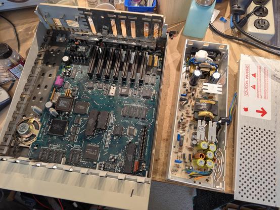
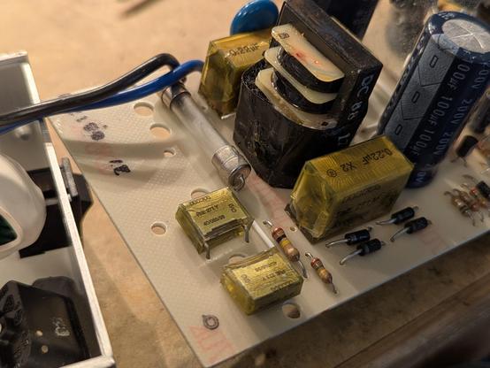
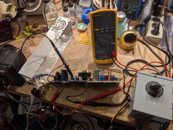
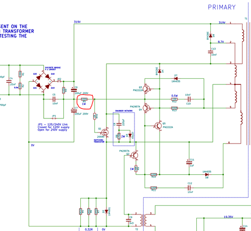
@tubetime This is an SMPS without a microcontroller or dedicated IC to handle the switching?

(Can't tell if the inductors on the right are supposed to have sine wave or square wave output.

Transformers coupling a square wave always bugged me b/c transformers only work for signals where the derivative is nonzero. But what's the derivative of a square wave? Well it's not a nice looking signal :P.)

@cr1901 yes no MCU or controller. i think it's hysteretic. schematic link is in another toot but you can see how the LM339 on the secondary side handles the regulation and pulse width modulation...

@tubetime For my uni controls project I built a fan controller. I wanted it to use PWM, so I built an op-amp controller in positive feedback configuration. Unfortunately, I only had 3 pin fans at the time, so PWM meant that I lost all the tachometer pulses during the "off" part of the cycle. So I had to put that aside :(.

(There's a way to convert a 3-pin fan to a 4-pin one w/ a dedicated PWM pin, but I don't remember it offhand.)