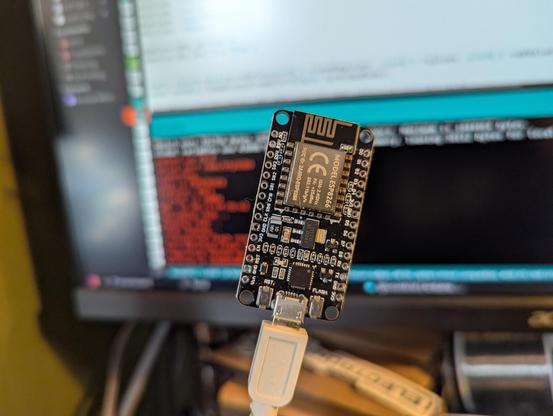
How is it that I have a half-dozen ESP8266 microcontrollers scattered around, and every single one of them has headers when I want one without?

How is it that I have a half-dozen ESP8266 microcontrollers scattered around, and every single one of them has headers when I want one without?
I built a GBS-C upscaler (https://ramapcsx2.github.io/gbs-control/)!
This is going to be a long thread, so I'm going to wait a few minutes before continuing to post, to give anyone who wants a chance to mute me.
🧵 1/24
Short version: upscalers allow you to connect old computers and video game consoles to modern displays, and make the output look good.
If you're not familiar with upscalers, sites like RetroRGB have a wealth of explanation: https://www.retrorgb.com/upscalers.html.
🧵 2/24

Upscalers If you prefer to play your classic consoles on a modern flat-panel TV, you can route your game system through a device that "upscales" the original resolution of your console into modern resolutions. For more info on resolutions, please see the 240p page. Quick Overview / Best Choic
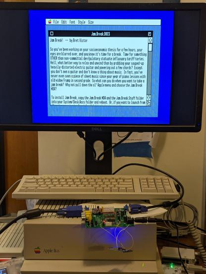
I have an Apple IIgs, and I have modern LCD monitors that will accept the old-fashioned 15 kHz video output from the IIgs via an adapter, but the picture never looks great. Usable, certainly, but not right.
🧵 3/24
(I do have a real CRT monitor that would be much more suitable, a 35 kg behemoth that I picked up from the curb last year. It was beautiful for 2 solid months, and then it wouldn't switch on one day: https://mastodon.social/@GamesMissed/112616999189476159. I'm somewhat afraid to try repairing it, but I really need to get around to it.)
🧵 4/24
There are lots of amazing upscalers for sale these days. I would love a RetroTINK 5X or 4K, but I cannot possibly justify the cost to myself. But a GBS-C upscaler involves soldering some additional cheap components to an already-cheap converter board. I have solder! I'm cheap! I gave it a go.
🧵 5/24
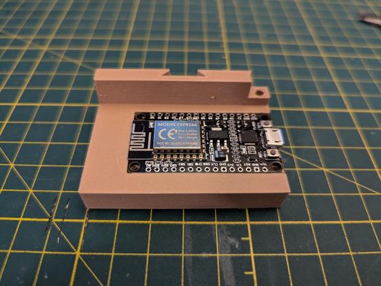
The GBS-C wiki (linked at the first post in this thread) is pretty good. All the necessary information is there, although it does require careful attention and I did need to read through some sections more carefully the second time around. First step after obtaining my components (thank you, gift-giving relatives!) was to program an ESP8266. I realized as I was doing so that I'd never worked with an ESP8266 before. It was very straightforward.
🧵 6/24
Once the ESP8266 is flashed, it starts running its own WiFI access point. If I connect to it with my computer, I'm supposed to be able to pull up the web interface at http://gbscontrol.local. This is extremely flaky, but just giving the access point IP (192.168.4.1) works reliably.
The interface looks a little cryptic, but see the question mark symbol next to "Resolution"? That's a button. Click on that and every single option gets a text explanation alongside or under it.
🧵 7/24

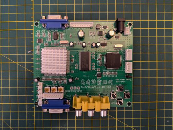
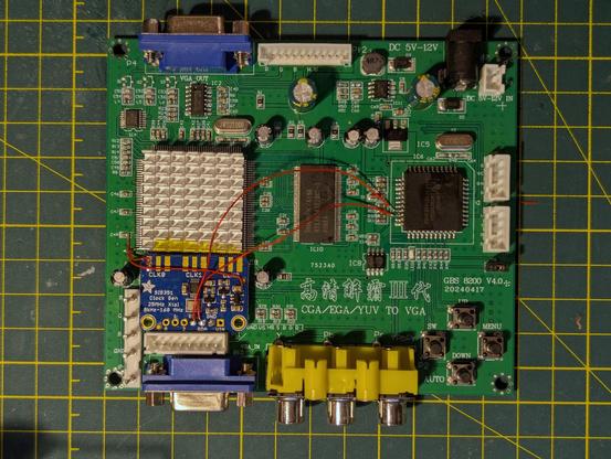
Now I need to do the actual soldering. This is the device that gets modified, a GBS 8200. It's intended purpose is to connect old arcade machine boards to modern display devices. Inputs are VGA and component (Y, Pb, Pr) video, 15 or 31 kHz, output is VGA, 15 kHz or 31 kHz.
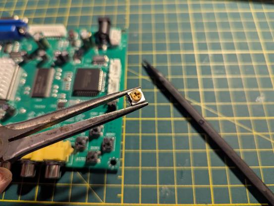
First step is to remove the potentiometers.
🧵 8/24
Interlude No. 1.
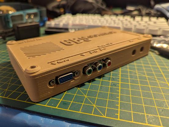
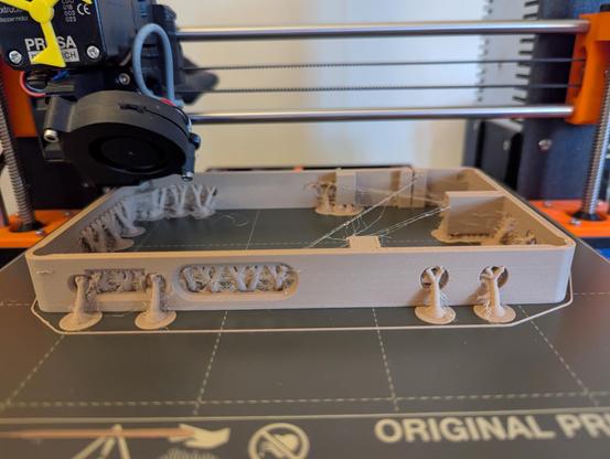
Since it'll take a while, this is when I started 3D-printing the case for my finished contraption. I went with this design off Printables: https://www.printables.com/model/152534-gbs-control-case-for-gbs-8200-with-bnc-for-rgbs. Because I might as well try multiple new things at the same time, I decided to print with 5-year old Hatchbox wood PLA. Yes, I buy too much printer filament. Fortunately, it's so dry here that it lasts a long time.
🧵 9/24

Back to (de-soldering). I get free potentiometers out of this! They're labeled as 500 Ohm, and seem to be close enough that I'll save them for re-use.
🧵 10/24
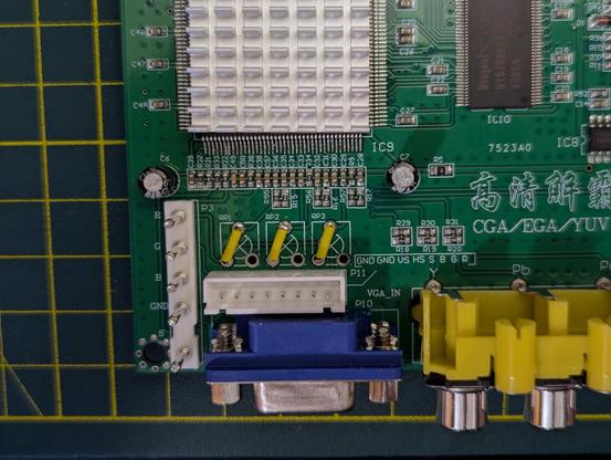
The instructions call for removing all three potentiometers from the input side of the board and bridging them, so that's done.
🧵 11/24
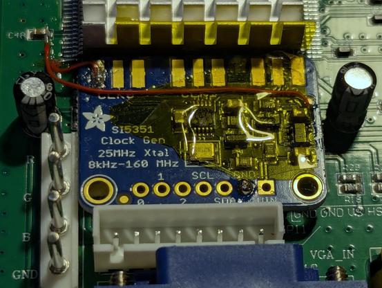
The clock generator board is an add-on to the GBS-C system, but it's easy enough to add. I started trying to do this work with wires taken from old Ethernet cables (24 AWG, stranded), but it was driving me nuts. I'm cheap, but I also don't want to be frustrated. I fished out my spools of 30 AWG solid wire and was a lot happier.
🧵 12/24
Interlude No. 2.
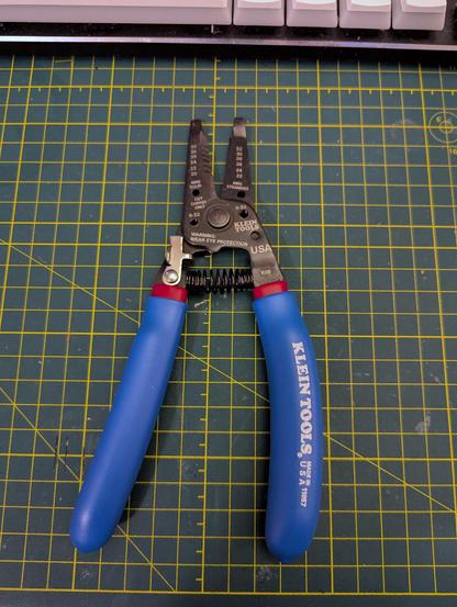
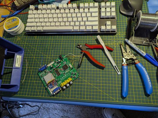
Speaking of not being frustrated, I took this as an opportunity to buy myself a new wire stripper, a Klein 11057 that will do gauges down to 30/32 solid/stranded. I had an old Ideal tool that would do 24/26, and you know what that's awful for? 30-gauge wire. The Ideal will go in the garage tool box, or I'll find someone to pass it on to.
🧵 13/24
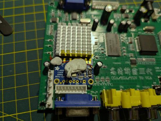
The clock generator soldered neatly into place. If you've built a GBS-C before, can you spot where I screwed up and didn't properly follow the instructions? I'll come back to that later on (or you can check the alt-text).
🧵 14/24
Interlude No. 3.
So, the five-year old Hatchbox wood PLA is, in technical terms, stringy as hell. But it isn't like normal awful-quality PLA stringing -- the strings crumble much like, well, sawdust, and it's not nearly as much of a pain to remove them and get the surface clean. I've never done much with wood PLA before, so this is all part of the learning process. It resembles an eldritch horror before post-processing, though.
🧵 15/24
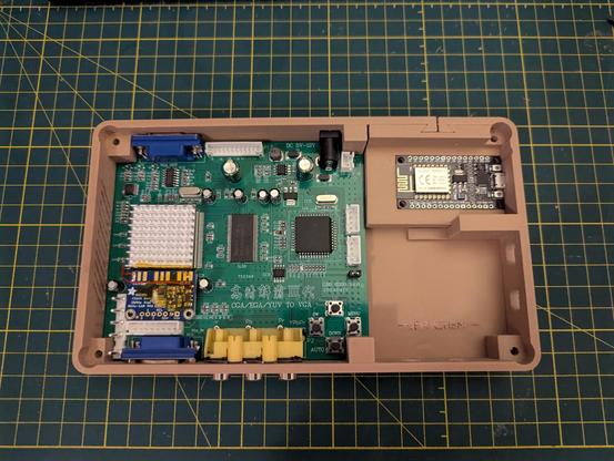
The case design for the finished scaler is *excellent*. Everything fits neatly, with just enough play in the components to get the electronics in place. The lettering at the bottom right of the case should read "JEFF CHEN," the designer, but the wood filament isn't complying so well with fine detail.
🧵 16/24

Some fine (scale, not quality) soldering work (by my standards, at least) to connect the clock generator to the Myson chip.
🧵 17/24

My desk, showing the project in progress, now with wires connecting the ESP8266 microcontroller to the GBS 8200. Everything's connected, moment of truth.
🧵 18/24
I interposed the GBS-C between my Apple IIgs and my Dell flat-panel monitor and plugged it in. And got nothing. This is the point where my previous error came back to bite me, and of course I didn't take any photos of it.
The web interface for the board was running, but I saw no response at all until I clicked "Pass Through," at which point I did get a picture, but it was terrible, warped and wobbly. Much worse than without the GBS-C inline at all.
🧵 19/24
A quick check of issues in the Github repository pointed to the clock generator board not working. I beeped out my solder joints, everything looked fine. So then I read through the assembly instructions again, and saw this, and then looked back at my work.
🧵 20/24


Not a terrible screwup. I was pretty far along didn't want to desolder the whole clock generator board in order to do the rework, but I used a fine tip on the iron and came at the joints from annoying angles, and managed to get it right the second time. The result?
🧵 21/24
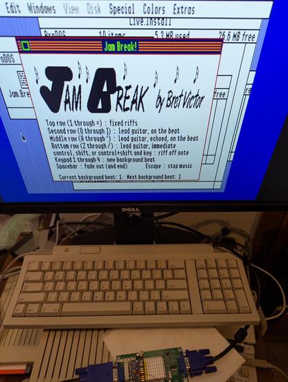
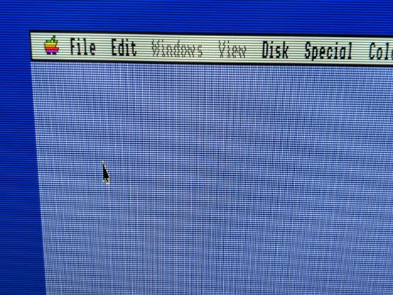
I'm not sure how well this comes across in the photos, but the display quality is *excellent*. No more artifacts or crawling. It's rock-stable and looks beautiful. The GBS-C can simulate scanlines, too, which can look especially nice with some applications.
(If you're getting a moiré effect, try viewing the image at full size. Sorry about that.)
🧵 23/24


I did also test the component input, hooking up my Gamecube and popping Mario Sunshine into the drive. The GBS-C handles that just fine, outputting clean VGA at 1280x960. But, I switched between the upscaled output and straight pass-through and didn't see much of a difference in the quality. I think the Gamecube's output over component cables is already pretty good (480p), so there's a lot less improvement to be had.
🧵 24/24
Summary:
GBS-C pros: easy to build if you're already the sort of person who keeps a soldering iron on their desk. Makes old computer displays look fantastic on a modern LCD display. $$CHEAP$$.
GBS-C cons: can't accept composite or S-video input, so can't be used with a lot of old video game consoles. I don't see much of an improvement from a Gamecube, which came out in 2001 and can already output 480p video over component video cables.
🧵 25/24 <sigh>
Things left to do:
1. Add the BNC connectors. There's a header on the board, right past the VGA input, to allow inputting RGB+S signals. I'm going to hack together a cable for the first time, to get RGB+composite sync out of my Apple IIgs' DB15 port and feed it into the GBS-C. It's why I chose the 3D-printed case that I did, because the designer had intended that option.
🧵 26/24
2. Stain the case. The reason I went with the wood PLA, as opposed to a normal PLA that doesn't print like a feverish nightmare, was to have a ludicrous faux woodgrain upscaler. Do you know what you're supposed to have when you apply stain to wood? Good ventilation. Do you know what the outside temperature is right now, as I type this? A balmy afternoon high of -8 C. Staining will wait, but I'll post the results afterward, good or bad.
🧵 27/24
A follow-up to this build thread:
A day after I posted all of this, I was having issues with the screen going black and then coming back again a second later. I pulled up the debug console in the GBS-C web interface, it showed that the microcontroller was resetting intermittently.
I opened up the case and took out the circuit boards. A quick inspection showed that I had a cold joint on the wire connecting the ESP8266 to ground on the GBS-8200 board. More attention with the iron solved that.
The build wiki recommends a 100 Ohm resistor between ground and sync, but the symptom it recommends that for is "No Picture" (https://ramapcsx2.github.io/gbs-control/Wiki/Build-the-Hardware.html#troubleshooting). I wasn't getting no picture, but a quick search showed that other people on the Internet had encountered similar problems and found adding the resistor to be a solution.
And it works! No more sync issues, and I've had the IIgs on for a few hours now.